|
A sensitive method of measuring small DC voltages.
The amplification and transformation of DC voltage and current has always presented special difficulties that are not present when dealing with AC. Many DC amplifiers have been described, but it would seem that only recently has really satisfactory apparatus been evolved, and now there appears to be a choice between a few types employing different principles, but each of value in its own particular sphere.
To mention what are perhaps the two principal types that have recently made their appearance, there is the one due to Stewart E Miller [1] Electronics, Nov. 1941, and Wireless World, May 1942. and the other due to D C Gall [2] Journal IEE, Vol. 89, Part 1, March 1942.. In Miller's amplifier, valves are coupled together by resistances in a particular way and special means are applied to eliminate zero drift. It would appear to be particularly valuable where high gain and extremely rapid response are required, combined with absence of zero drift. A flat response from zero to 12 kHz at an output of ±80 Volts and ±5 mA for an input of only 0.35 mV is clearly an excellent performance.
Gall's amplifier is different in principle and purpose. In this case, too, we have high gain and stability, but we have also a heavier power output, particularly suitable for operating commercial recording instruments. As the operation depends initially upon the movement of a galvanometer mirror which reflects a beam of light on to a photo-electric cell, there must necessarily be a small time lag and there is no question of comparing frequency response, but the time lag is too small to be of any consequence in the operation of commercial recording instruments.
Each of the above amplifiers has its own particular sphere and both indicate a good deal of careful work and ingenuity.
The amplifier to be described in this article employs yet another principle and may perhaps find its own particular sphere of usefulness. In its present form it gives an AC power output for a small DC voltage input, so that the output can be readily transformed to give any desired combination of voltage and current and may be converted to DC by the aid of a rectifier if desired.
The chief component is a device for converting the DC into AC, which is then amplified in the usual way. There are many ways in which DC may be converted into AC, or be made to control an AC supply, and the writer has adopted a principle which he used in some experiments on magnetic polarisation in 1937, and described in a subsequent paper. [3] Journal IEE, Vol. 84, No. 505, Jan. 1939.
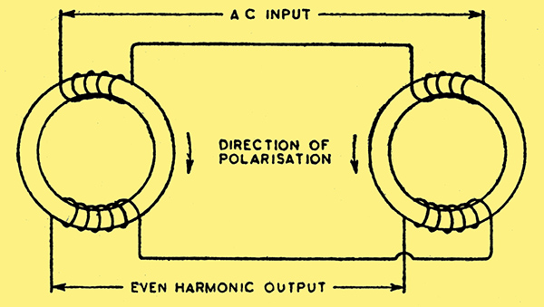
Fig. 1. Circuit for separation of even harmonics.
In a particular experiment, certain ring-shaped specimens of Stalloy were known to be polarised while subjected to AC magnetisation, so that the voltage across a secondary winding contained even harmonics. It was desired to separate the even harmonics from the fundamental and odd harmonics and so examine the even harmonic content alone. This was done by using two exactly similar specimens and so connecting their windings that in the secondary windings the odd harmonics opposed one another while the even harmonics were additive. Fig. 1, showing the connections and direction of polarisation, will make the principle clear. If the cores are not polarised there will be no output.
In the original experiment, the polarisation was maintained by tuning the secondary windings to the second harmonic frequency, but it is clear that the cores may be polarised by means of DC in the existing windings or in separate windings provided for the purpose The output will then depend upon the DC magnetisation. If a rectifier be added to the secondary circuit we shall have, in effect, a DC transformer, the relation between DC input and DC output depending upon the turns ratio.
This arrangement alone can be put to many uses, but for our present purpose we do not need a rectifier connected to the secondary winding. The AC harmonic output is caused to operate an AC amplifier and may then be rectified if desired. It is clear that a large range of input and output values can be made available by varying the windings.
It is perhaps better to call this piece of apparatus a DC/AC converter, rather than a DC transformer, except when a rectifier forms an integral part of the secondary circuit. Whether or not the converter is to be used with an amplifier, the DC may be fed direct to the input winding, but if this is done a series choke should be used in order to prevent the circulation of even harmonic current in the input circuit. In many cases it is preferable to feed the input winding through a valve stage. This serves to isolate AC voltages from the input DC and to give a very high input resistance. It can also provide a considerable proportion of the overall amplification. The possibility of zero drift due to this valve stage must not, however, be overlooked and suitable precautions would need to be taken if the amplifier were designed for a very high gain. The double-triode arrangement used by Miller could no doubt be put to useful service in this connection. Up to the time of writing no attempt has been made to ascertain experimentally the highest practicable gain from an amplifier of this type and very many possible modifications in detail suggest themselves.
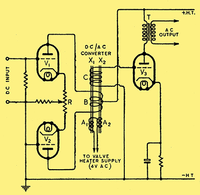
Fig. 2. DC/AC converter with high-impedance valve input circuit.
A simple circuit arrangement is shown in Fig. 2. Two valves V1 and V2 are used on the input side, as the current through the two sections of winding B on the DC/AC converter must normally be balanced in order to avoid initial polarisation. A variable tap on the resistance R serves to adjust this balance.
The results obtainable from such an amplifier depend principally upon the design of the DC/AC converter. There are many possible alternatives in the form and material of the cores, and the numbers of turns on the windings may be altered within wide limits to suit circumstances. The main factor that would appear to limit the possible amplification is the difficulty in obtaining a perfectly true magnetic balance in the two cores when there is no DC in the winding B. Fortunately, however, a small magnetic unbalance can be corrected by suitable adjustment of R.
The difficulties of obtaining magnetic materials at present has limited the experimental work to some extent, but the writer had a few Mumetal stampings and these were found to give good results. The best results were obtained by overlapping the stampings [4] For further comments on this mode of assembly, see article on Magnetic Hysteresis Loops, in the Electrician, Aug, 21st, 1936. in the manner shown in Fig. 3, in which their dimensions are also given.
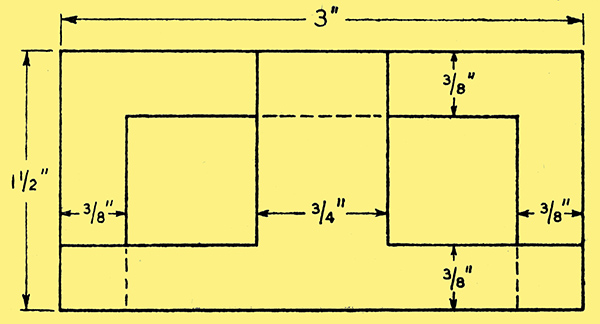
Fig. 3. Method of overlapping stampings in the converter core.
Five stampings - three Tbs and two U's were thus arranged for each of the cores X1 and X2.
The core section and winding space available were limited by these stampings and the effectiveness was found to be considerably enhanced by interposing an ordinary inter-valve transformer between the winding C and the output valve V3.
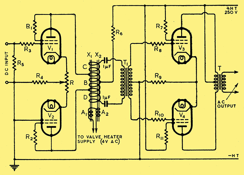
Fig. 4. Practical circuit with values suitable for use with KT41 valves throughout, R1, R2, R7, R11 = 200 Ω, R3, R8, R10 = 30 Ω, R4 = 100 Ω, R5 = 500 kΩ, R6 = 8 kΩ, R9 = 50 Ω. Potentiometer R = 30 Ω.
Very good results have been obtained with the circuit shown in Fig. 4. Here it will be seen that the two windings B and C are replaced by an 'auto-transformer' winding divided into sections and coupled to the output valves through an inter-valve transformer. The output valves in this case are KT41 tetrodes in push-pull. The input valves V1 and V2 are also KT4I tetrodes, but are connected as triodes. The effectiveness of these valves for the input side of the converter is due to their high mutual conductance. The grid voltage range required is very small and it is possible to effect an appreciable economy in HT requirements by inserting a resistance R6 of 8 kΩ in series with the common anode supply t0 these valves. The total HT then required for the four valves is 120 mA at 250 V.
The AC exciting windings A1 and A2, Fig. 4, each comprise 800 turns of No. 38 SWG. The DC winding B is wound in two sections, each having 3,000 turns of No. 43 SWG. This winding B, together with the end sections C and D, also forms the AC output winding. The sections C and D each have 1,000 turns of No. 43 SWG. All windings are enamelled copper wire.
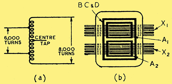
Fig.5. (a) Circuit connections of main winding, and (b) Section showing arrangement of windings on cores of converter unit.
The main winding is shown more clearly in Fig. 5 (a), while Fig. 5 (b) indicates in section the general arrangement of windings on the cores. The inter-valve transformer T1 was an old Marconi 'Ideal'b of 2.7:1 ratio.
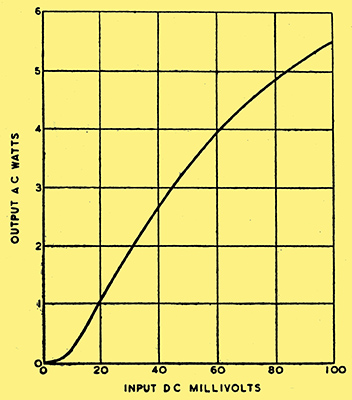
Fig.6. Characteristics of circuit shown in Fig. 4.
The results obtained with the circuit set up exactly as described are shown by the curve in Fig. 6, in which output AC Watts are plotted against input DC millivolts. The curve is only taken to 100 mV input as this is considered to be the useful range. The output at 100 mV input was 177 Volts, 31.5 mA RMS, or just over 5.5 Watts, from a 2:1 step-down transformer. Beyond this the curve gradually flattens out to a saturation value of 8.5 Watts output at about 600 mV input. The output waveform at 100 mV input as observed on an oscilloscope is shown in Fig. 9. The fundamental output frequency is 100 Hz when the excitation frequency is 50 Hz.
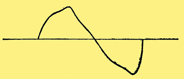
Fig. 9. Observed output waveform for a DC input of 100 mV.
DC Feedback
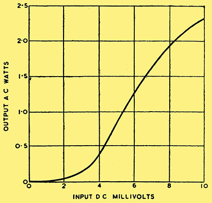
Fig. 7. Increased sensitivity results from the use of DC feedback as shown in Fig. 8.
The sensitivity may be greatly increased by the use of DC feedback as shown by the curve of Fig. 7, which is plotted to 10 mV only, this being the useful range under these conditions. The necessary circuit additions are shown in Fig. 8.
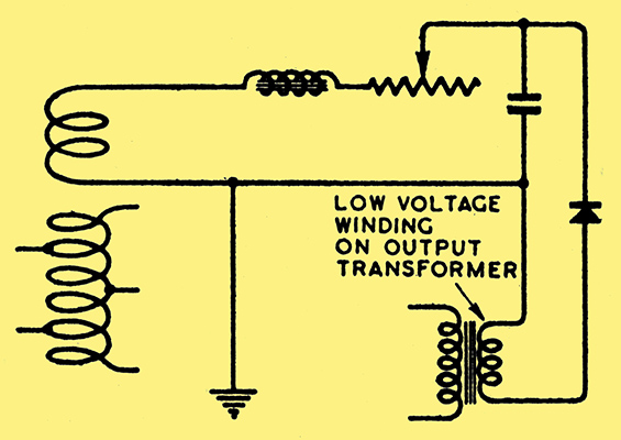
Fig. 8. Elements of additional DC feedback circuits.
The feedback was not pushed to anywhere near the point of instability, so that this does seem to be quite a practical way of increasing the sensitivity. It is perhaps open to argument, however, whether this method of increasing the sensitivity of an instrument, in which maintenance of accuracy and reliability are of importance, is as satisfactory as the addition of an extra stage of AC amplification.
It is clear that an instrument of this kind should be fed from a stabilised AC supply. Not only are HT volts of some importance, but heater temperatures and AC exciting volts for the converter should be constant.
It is recommended that calibration should be done with input polarity as shown in Fig. 4, and the same polarity must be adhered to in subsequent use. It should also be noted that the DC/AC converter is very sensitive to external magnetic fields, whether alternating or uni-directional. It should, therefore, be sufficiently distant from either mains trans- formers or permanent magnets. Clearly, a good magnetic screen would be an advantage.
The usual precautions apply as regards stability of resistance elements in the amplifier, and the input grid lead should be protected from AC fields by screening. It is also worth while to screen the input valves. A capacitor of, say, 1 μF connected across the input terminals as an AC bypass is a useful further precaution when the conditions are such that it will not introduce an appreciable delay in the response.
References
- Electronics, Nov. 1941, and Wireless World, May 1942.
- Journal IEE, Vol. 89, Part 1, March 1942.
- Journal IEE, Vol. 84, No. 505, Jan. 1939.
- For further comments on this mode of assembly, see article on Magnetic Hysteresis Loops, in the Electrician, Aug, 21st, 1936.
|