|
Effects found on Short-Wave.
The Mullard EK3.
Abstract
It is well known that, in an, octode frequency-changer, it is the second space charge which enables multiplicative mixing of the input frequency with the self-generated oscillator frequency to be accomplished. However, another unforeseen effect of this space charge is to couple the input circuit to the oscillator circuit, which causes the gain of this stage to be dependent on frequency. The phenomenon is studied, and explained by influence effect of the second space charge. The dependence of the anode current on frequency, shown by experimental results, is theoretically proved. Means are indicated whereby the frequency dependence of the gain is corrected. As an application of the theory, an oscillator is described which functions by virtue of the principle of influence, and from this the production of parasitic oscillations in an octode is explained.
The phenomenon, to be described in this article, occurs in some frequency-changer valves which perform the combined role of modulator and oscillator. Typical representative types of valves are heptodes and octodes.
American designers found that the gain of a heptode depended on wavelength. If the tuned circuit attached to grid 4 of the valve is short-circuited means of a capacitor or conductor, the same anode current is observed as at long waves, but when the grid circuit is not short-circuited the anode current is different.
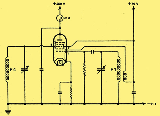
Fig. 1. The basic circuit diagram of the Octode, frequency-changer is shown here.
In order to study the phenomena, the circuit shown in Fig. 1 was arranged with an octode valve; in the mechanical design of the circuit, allowance was made for independent operation of the variable capacitors of the input and oscillator circuits. The anode circuit contains a milli-ammeter.
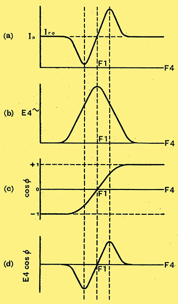
Fig. 2. The variation in anode current with tuning is shown at (a), and the voltage at grid 4 at (b). The variation of the cosine of the phase angle between the voltages on grids 1 and 4 is shown at (c), and at (d) the calculated change of anode current.
In Fig. 2 (a) is shown the variation of anode current as the input circuit capacitor is rotated, the oscillator capacitor remaining constant. If the resonance frequency of the input circuit differs largely from the oscillator frequency, the anode current has a value of approximately 1 mA. As the difference between the input circuit frequency and the oscillator circuit frequency decreases, so the anode current falls and achieves a minimum, then rises again rapidly to a distinct maximum. As the frequency of the input circuit is increased still further, the anode current again drops asymptotically to the same value as it had at the beginning. At the point where the oscillator and input circuit frequencies are identical, the anode current of the valve is normal.
The frequency dependence of the anode current undoubtedly originates from an alternating voltage, built up on the tuned circuit of the fourth grid. An explanation will be given of how this alternating voltage arises, and how it causes a variation in anode current.
The transference of the oscillator frequency to the input circuit is caused by electron coupling. Besides the primary space charge in a valve having many grids, in which the grids have different potentials and polarities, a second space charge will occur. Thus, in an octode a second space charge occurs between the third and fourth grids. The formation of this is caused by the decelerating action bf the negatively biased fourth grid. Similar space charges have in the past been referred to as virtual cathodes. Besides the fact that such space charges can be controlled in a similar manner to the space charge surrounding the real cathode, they share the property of all electrical charges of producing in neighbouring conductors other electrical charges due to their influence.
An alternating influence charge occurs on the fourth grid by virtue of the periodical variation in the second bspace charge, which oscillates in sympathy with the voltage on the first grid. The influence charge causes as current to flow in the circuit of grid 4, which builds up a voltage which, as shown below, is there reason why the anode current depends on frequency. That the current variations shown in Fig. 2 (a). really occur is conformed by the examination of the phase relationships.
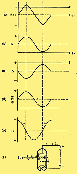
Fig. 3. The voltage on grid 1 is shown at (a) and the corresponding current at (b), with the variation in space charge at (c). The charge induced on grid 4 is given in (d) and the resulting grid current at (e).
The individual factors that have an effect on the phase of the alternating voltage in the circuit of the fourth grid are shown in Fig. 3. The sequential variation of voltage on the first grid is shown in Fig. 3. (a); the valve current (Ik) flows in phase with the above Fig. 3. (b), Whilst the space charge is 180° out of phase. This is very easily appreciated if one considers that when the current flows a greater quantity of negative electrons pile up in the space between third and fourth grids Fig. 3. (c). As the sign of the induced charge is opposite to that of the space charge Fig. 3, (d), it is again in phase with the alternating voltage on grid 1. The current caused by influence leads the charge on grid 4 by 90°. This is the result of the fact that the direction of the current is positive when the influence charge increases, and becomes negative when it decreases Figs. 3. (e and 3f).
The frequency and magnitude of the anode current variation can be resolved from the following consideration; the anode current variation has zero frequency, as the alternating voltages on the first and fourth grids, which produced this variation, are of the same frequency; the anode current variation is proportional to the amplitude of both alternating voltages. If we indicate these values, in sequence, as E, and E4, then the anode current is given by the well-known formula:-
ScE4cosφ.
Here φ indicates the phase-difference between the two voltages. So is the conversion conductance of the valve. The latter value contains the amplitude of the oscillator voltage, and as the oscillator circuit constants do not alter it is a constant. Thus, the anode current variation is proportional to E4cosφ.
In order to calculate the latter expression, one requires to know the phase angle. This can be arrived at from the following:-
As is known, a relationship exists between the phase of the control voltage and the instantaneous value of anode voltage, which is best shown in a tabular manner, as follows:-
The same relationship exists between the control voltage and the voltage on the fourth grid, remembering that the voltage on the fourth grid leads by 90°. The latter is a consequence of influence, which was responsible for the voltage on the fourth grid. Thus, we find the following phase relationship:-
The load resistance of the circuit of the fourth grid is pure ohmic if F4 = F1; inductive if F4 > F1; capacitive if F4 < F1, Where F4 indicates the natural frequency of the input circuit, F1 the natural frequency of the oscillator circuit. The phase angles are, in consequence, 90°, 180° and 0°.
From these values we can calculate the anode current alteration from the expression E4cosφ. Thus, Fig. 2d was calculated, which, as will be seen, is identical with 2a. The theory that the anode current is a function of frequency is thus confirmed. From this theory we can draw the following conclusion, that it is possible to compensate for the decrease in gain of a mixer valve, by impressing upon the fourth grid an alternating voltage of the same magnitude but of opposite phase to that produced by the influence of the space charge coupling. If one introduces a small capacity between the first grid and fourth grid, then a voltage is transferred to grid 4, in phase with the voltage on grid 1, provided the impedance of the fourth grid circuit is mainly capacitive, but in opposite phase if the impedance is inductive. The voltage produced by the small capacitor is 180° out of phase with the voltage induced by space charge coupling.
The compensating capacitor will have a constant value over the whole waveband provided that the modulation coils stay constant.
An Oscillator Circuit
We have found that a capacitance of approximately 2 pF is sufficient to achieve the required compensation in a Tungsram Octode, TEK2 (VO6s), on the whole wave range from 20-50 metres. Hence, a small capacitance is actually built in to type'TEK2 (V06s).
This effect, which is usually an unwanted one, can sometimes be turned to good account, and an application of.it is described by C J Bakker and G de Vries, in an article in Physica, Vol. 1, 1934. Pages 1045-1054.

Fig. 4. The basic circuit of an 'influence' amplifier.
The circuit principle is shown in Fig. 4. For the sake of simplicity all electrodes of the octode not affecting the action are omitted, the remainder forming a tetrode whose anode has a negative voltage. The space charge which oscillates in sympathy with the frequency of the voltage on the first grid sets up an influence voltage on the anode, which causes a current to flow in the anode circuit, which can be further amplified. In this article the theory of the influence amplifier is described, and in order to be able to include the Short-Wave lengths in this consideration the finite transit time of the electrons between screening grid and anode is included in the calculation. Experimentally, the theory was confirmed on various Wavelengths (namely, at 6, 15, 25 and 50 metres). Besides this, the above authors constructed a three-stage amplifier which, in principle, utilised the circuit shown in Fig. 4. The amplifier worked satisfactorily on wavelengths between 15 and 50 metres.
The advantage of the influence amplifier is that it is not necessary to use a capacitor-resistance coupling between stages.
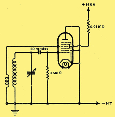
Fig. 5. An oscillator circuit making use of the 'influence' effect.
In the Tungsram Research Laboratory an attempt was made to evolve an oscillation generator from the influence amplifier. By the orthodox method the voltage produced on the fourth grid was fed back to the first grid Fig. 5. The second grid and anode of the octode were returned to cathode, the fourth grid being connected to the cathode via the reaction coil. It was found that this arrangement permitted the production of wavelengths between 3 - 15 metres. At higher wavelengths, apparently, the amplification is insufficient to compensate for the losses in the oscillatory circuits.
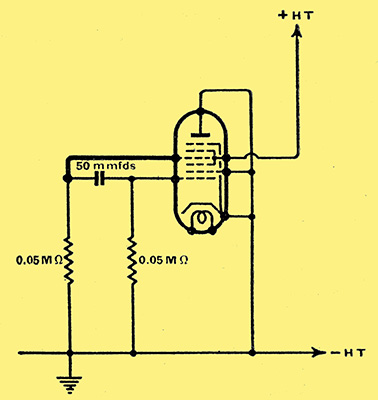
Fig. 6. Oscillation can be secured at very high frequencies with this circuit.
In order to produce waves of even shorter length a relatively thick wire was directly connected between the fourth and first grids. In this circuit, which is basically a Colpitt's reaction circuit, the tuning capacity and the three-point division of the tuning circuit are obtained by utilisation of the valve capacities (Fig. 6). The shortest wavelength obtainable with this circuit was 1.5 metres. The fact that short waves can be produced in this manner explains the phenomena of parasitic oscillations in mixer valves. The usual explanation put forward for these parasitic oscillations is that the slope of these valves is too high. This assumption does not hold, however, as the slope of the octode is well below that of an output valve.
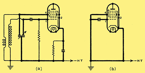
Fig. 7. Parasitic oscillation can be caused by the 'influence' effect, oscillation taking place in the part of the circuit shown in heavy lines.
However, if one looks upon the octode as an influence amplifier, the production of parasitic oscillation can quite easily be visualised. The lead of the fourth grid acts as the inductance for the ultra-short wave oscillatory circuit. The impedance necessary for reaction is the common cathode lead of the tuning capacitors of grid 1 and grid 4. Fig. 7a shows this circuit diagrammatically. The parts of this circuit of importance in the generation of oscillation are shown in heavy lines. Fig. 7b simplifies this circuit farther to show its similarity to Fig. 6.
The disadvantageous effect of the parasitic oscillation which can cause a reduction or discontinuation of local oscillation can be obviated, as suggested by Barkhausen, by introducing a small resistance into the cathode lead of the fourth grid. This resistance should be non-inductive and non-capacitive.
|