|
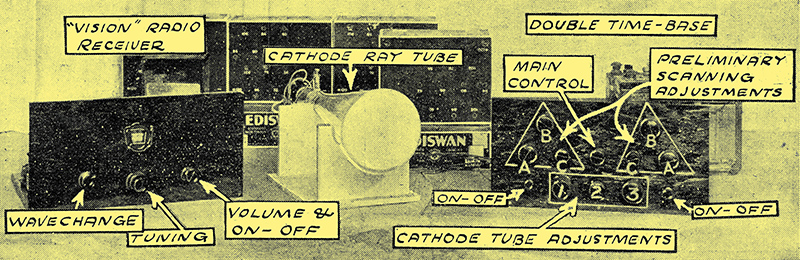
The complete receiver.
The System of the Future
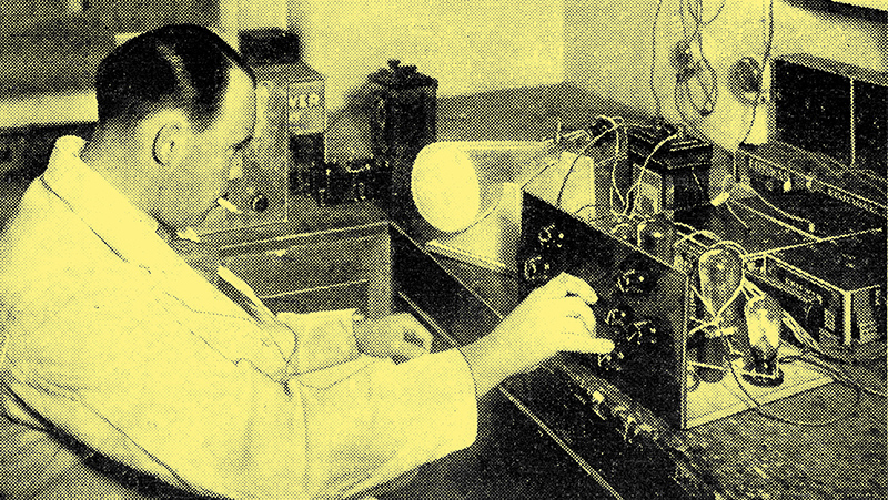
The author at the bench. Note the accumulators for the LT and the two HT batteries behind the chassis -ed.
In our opinion television progress has been seriously hampered, both at the transmitting and the receiving ends, by the various limits placed upon it by the use of mechanical scanning, and though a certain amount of progress has been made with unwieldy mechanical devices, We feel that it is not from them that the final perfected form will emerge.
The development of the cathode ray oscillograph, however, in which Ediswan have taken a large part, has offered at complete break-away from mechanics, at least in the reception of television, and, after a considerable amount of research on the subject, we are convinced that the electronic method or picture formation will definitely constitute the basis for the perfected television receiver of the future, and the details we are about to give will enable readers to go straight ahead on the right lines with the reception of television broadcasts.
The complete controllability and negligible inertia, of the free electron contrasted against the rigid stubbornness of the mechanical scanning device, with its sluggish variation of the source of illumination points very clearly to the former as the solution to the many problems that beset experimenters in television especially radio television.
In the mechanical receiving systems scanning is carried out by rotating discs or mirror drums, the synchronising depending on the accurate speed control of a comparatively cumbersome and unresponsive electric motor, while the variation of the light source that is to supply the image is a matter of the rapid control of a comparatively insensitive glow lamp by means of a powerful amplifier delivering heavy impulses.
A Double Duty
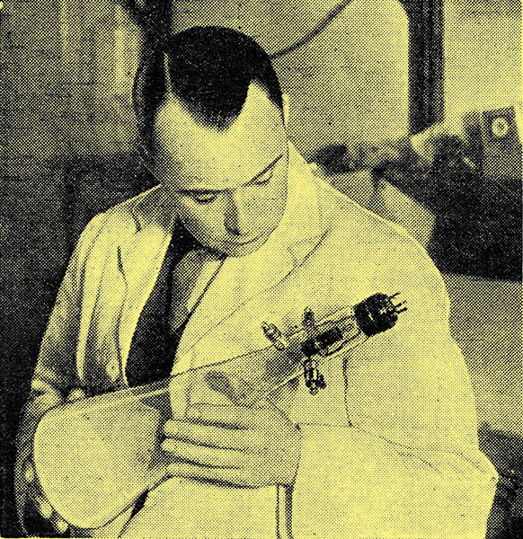
The Chief of the PW Research Department, Mr K D Rogers, examining one of the new Ediswan Cathode Ray Television Tubes, used during his experiments. Synchronisation is under complete and accurate control, and its adjustment is the work of only a moment.
In the cathode ray system the tube is in itself the scanning device and source of illumination, and the control of a, stream of electrons is a far easier task than the variation of the speed of at motor, and the modulation of a discharge lamp.
Other great advantages in favour of the cathode ray method of reception rapidly appear as it is more closely examined, one of the most important being the fact that it is applicable to any television transmission (as long as it is of the intensity variation type which is universally used to-day) Without any but the most trivial alterations to the receiving circuit.
Such adaptability is impossible with the mechanical method, with its elaborate synchronising and scanning systems, while the ridiculously small input required from the receiver to the cathode tube compares very favourably with the thousands of milliwatts needed for the mechanical viewer.
Small Input Needed
As will be seen from this general view of the apparatus and the diagram below, stark simplicity characterises this ingenious method of television reception. Instead of using moving mechanism, the electron stream has been harnessed to provide a bright moving image of the events transmitted from the studio. This image is of such clarity that from six to a dozen people can comfortably watch the reception, there being no need to crowd round the screen at all.
As a matter of fact, the cathode ray television viewer which we introduce to you here requires but a matter of a, few Volts from the radio set; it is a voltage operated device and, as such, hardly consumes any power at all. The result is that a three or four-valve. set of the economy battery operated type is ample for the full modulation of the television viewer, in consequence of which the whole receiving outfit is as simple to build as an ordinary radio set.
But let us start at the beginning so that you may see exactly how the cathode-ray television receiver operates, and can judge for yourself how very, very simple the whole thing is.
A universal scanning system.
We must make it clear, however, that the system of reception that we are going to describe in this and subsequent articles, while not perfect, is yet a very efficient step towards our goal, and will undoubtedly provide the final solution to the problems of television reception.
It provides truly excellent results, though these results are necessarily restricted by the shortcomings of the transmissions at present available at any rate in this country, which shortcomings include the limitation of the modulation frequency band clue to the congested state of the ether on the wavelength bands now used.
Adaptability
With short wave broadcasts the frequency band transmitted could be very much wider, and consequently greater definition could be transmitted, with more rapid scanning. This would result in very much clearer and more detailed pictures, but should this change be made tomorrow the cathode ray receiver could be instantly adapted to the new conditions. The mechanical device would be useless until it had been redesigned and rebuilt. Even then it would be doubtful if it would be of much use, for the rate of mechanical scanning is restricted by purely mechanical limits of inertia, bulk, and centrifugal force.
The cathode ray has no such limits, and its lively beam can be scanned at incredible speeds, by the mere turn of a knob, or by the same means reduced to the regular time pulsations of a clock's pendulum.
During the experiments undertaken by the PW Research Department in cathode ray reception, the Ediswan tube has been taken as a basis of research, and Messrs. Edison-Swan have worked closely in collaboration with us in the design of cathode ray tubes to suit the various experiments carried out, and a great deal of our undoubted success must. therefore be attributed to them.
Can be Confidently Recommended
The final tube, which is illustrated, is the result of much experiment and experience, and can be confidently recommended to readers who wish to carry out television reception. of their own.
The fundamental operation of the cathode ray tube is fairly well known: how the electrons given off from the cathode are accelerated by means of a positively charged anode and how they shoot through a hole in the anode, race up the tube and impinge on a specially prepared phosphorescent screen. At the point of impact a spot of light (of a greenish blue colour) appears.
In order to get the electrons to keep together and form a focused beam a metal shield is placed round the cathode, forming a cylinder, and this is supplied with a negative bias (relative to the cathode). This has the effect of repelling the electrons, and so forcing them to bunch together, instead of spreading out, as they would if allowed to come off the cathode uncontrolled.
Thus they shoot through the anode, or accelerator, in the form of a closely knit beam. The result on the screen is a brilliant round spot of light.
Tracing Patterns With The Beam
So far so good. The next thing is to control this beam so that it shall trace patterns on the screen, our ultimate aim to be a picture.
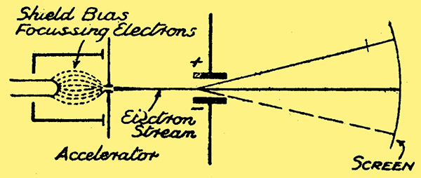
Fig. 1. Showing how the Cathode Ray is focused and deflected by applied voltages to shield and deflectors.
If we place a couple of metal plates on either side of the beam, as shown in Fig. 1., we can, by applying a potential across the plates, deflect the beam either in one direction or the other. The electrons are attracted by the positively charged plate (it is positive in regard to the opposite plate) and repelled by the negative plate.
The beam therefore bends upwards (see Fig. 1). If we reverse the potential on the deflectors the beam is bent downwards (see dotted line). In practice the potentials of the deflectors are relative not only to one another, but to the accelerator, but that we need not go into at this juncture.
We have been able then to deflect the beam in one direction, and if we were to apply, a varying potential to the two deflectors we could make the beam travel rapidly enough to trace a luminous line on the screen.
This could be termed 'scanning' the beam in one direction. For television, however, we have to scan in two directions, to correspond with the scanning applied at the transmitting end. The exact whys and wherefores of this we need not go into here.
Two Sets of Deflectors
Obviously we cannot do that with the two deflector plates in our possession at the moment; we need two more. These are placed at right angles to the first two, and slightly further down the tube.
Now, by the same rules of the game, we can with the new plates make the beam traverse the screen in a line which is at right angles to the first. That is done by applying potentials to the second pair of deflectors.
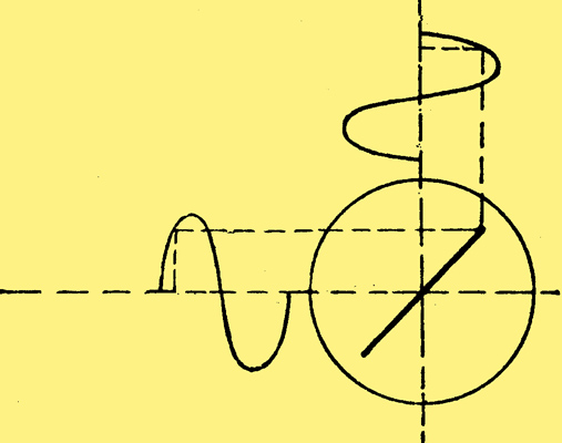
Fig. 2. With two more deflectors at right angles to those in Fig. 1, the scanning of the beam can be tilted as desired. The figure shows the effect of AC potentials on both pairs of deflectors.
If we apply potentials to the four plates, the potentials being arranged across pairs, we can trace all sorts of patterns with the beam. For instance, pure AC potentials applied together, in phase as in Fig. 2, would produce a line of travel of the beam that is 45 degrees to the axis of the deflectors.
So we see that we have a great deal of scope as to the movability of the electron beam, and we can now devise a method of making that beam scan the screen in same way as the television transmitter is scanning the object being televised.
This scanning consists basically of a series of vertical traverses carried out across the object in thirty strips, so to speak. In other words, the cathode beam has to travel down the picture thirty times, forming thirty separate lines, to, complete one scanning of the picture. (we are taking the Baird system of transmission for our basis of, experiment.)
Thirty Vertical Lines
Thus the beam has to go down the screen, return, and go down again a little further on until it has done so thirty times. On top of this it has to carry out this procedure at the rate of twelve and a half times per second.
How is this to be accomplished? In the first place, let us consider the vertical scanning alone leaving the question of moving the traversing to the left for each scan as we have to do in order to get a picture.
The vertical traverse of the beam must be carried out at a definite rate, which must be constant. Moreover, its return to the beginning for the commencement of the next traverse must be instantaneous and not visible. It must apparently be unidirectional.
Now, referring back to Fig. 2, we must note that the scanning of the beam is not carried out at a steady rate. At the tops and feet of the curves denoting applied deflector potentials the beam slows down and becomes stationary for a fraction of a second. The point of fastest travel is where the curve crosses the axis, that is half way across the line traced on the screen of the cathode ray tube.
We must arrange for the purposes of television that the speed of the beam in its straight line traversing is constant. This is done by what is known as a 'time base'. Theoretically, in its simplest form, this consists of the application of a steadily increasing potential across the deflector plates concerned, so that the bias of the plates is constantly increased. (we actually work with a system that decreases a steadily applied negative bias relative to the accelerator rather than one that increases a positive bias, but that is a practical refinement and does not alter the theory.)
Linear Increase Needed
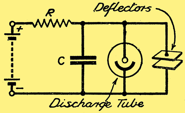
Fig.3. The fundamental circuit of a time-base for scanning.
The circuit shown in Fig. 3 would apply the increasing voltage, only it would not be quite a linear increase. The deflectors are joined across the applied potential in series with a resistance, Across the potential is also a large capacitor, which charges up at a rate which is determined by the value of the resistance and the voltage. The size of the capacitor determines the time taken for complete charging to be accomplished.
As the capacitor charges so the voltage applied to the deflectors increases, and accordingly the beam moves across (or down) the tube.
Actually with a resistance the rate of charge of the capacitor, and therefore the rate of potential in-crease across the deflectors, gradually slows down as the capacitor becomes fully charged. In practice we use a diode valve instead of the resistance, so that the rate shall be more nearly perfect in linearity.
But a resistance will give the desired effect for the purpose of explanation. When the capacitor is charged the potential across the plates is at maximum and the beam stops its travel. We have completed a line on the screen at a definite rate.
Now we have to get back to the beginning and do the traversing again. But we have to return unseen!
Use of Discharge Tubes
The way this is accomplished is one of the prettiest schemes devised. Across the capacitor in Fig. 3 We connect a discharge tube, which will suddenly discharge when a certain potential is applied across it. In practice this is arranged by using a discharge tube with a grid control (a thyratron), but the two-electrode tube shown in Fig. 3 illustrates the fundamental idea.
At a certain potential, that is when the beam has reached a certain spot, the discharge tube (filled with mercury vapour) flashes over. The capacitor is discharged, and the voltage across the deflector plates is lost. The beam has returned to the start of the line at incredible speed, invisibly.
Immediately the potential begins to rise again due to the capacitor commencing to recharge, and we have the same sequence repeated.
Shown as a Graph
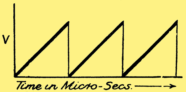
Fig. 4. Steady charge on the capacitor in a timebase causes-the beam to travel as shown by the heavy lanes above. The thin vertical lines denote the instantaneous return of the beam on the removal of potential across the deflectors.
The result in graph form is that of Fig. 4 where the slow charging is shown plotted against time and voltage rise, and the instantaneous return due to discharge of the mercury vapour lamp is shown as a thin vertical line.
We have achieved a series of uni-directional scanning, the first step towards true television reception.
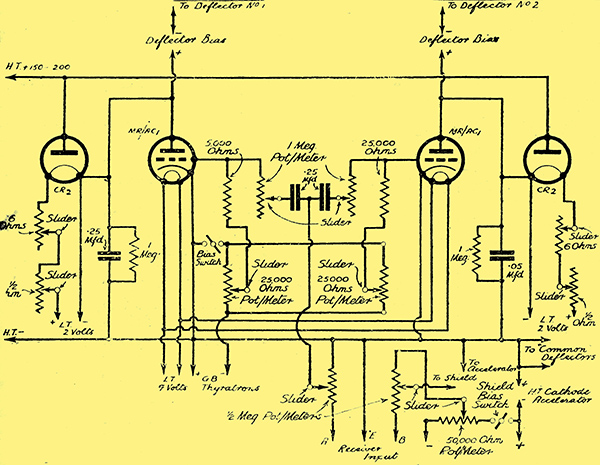
It now remains to move the beam a definite distance to the left as each line is completed. This is done by a similar timebase operating at a slower frequency across the second pair of deflectors (i.e. at right angles to the first pair), twelve and a half per second being the time for horizontal scanning for this time-base.
As the vertical scanning is carried out at a rate of thirty times for each one of the horizontal scans, we have a total rate for the vertical scanning of twelve and half times thirty; or 375 times per second.
Thus we have two timebases in operation simultaneously, one operating with a discharge rate of twelve and a half and the other a rate of 375 times per second. This gives us the correct scanning pattern for the Baird television transmissions.
A Practical Application
We are now going to describe the practical application of that tube so that you can go straight ahead on the construction of a really practical television viewer.
We should like to stress the practical aspect, for not only is the cost of the components quite moderate (especially as many readers will have many of the required parts already in their possession), but the possibilities of the system for future development are enormous.
Return to series start
|