|
We have now reached a most interesting stage in the construction of the Popular Wireless Cathode-Ray Television Viewer - that of assembling the various sections forming the complete outfit. The connections for testing out the viewer prior to fitting it into its cabinet are fully described.
A notable advance has been made in television, thanks to the efforts of al young Londoner. It brings nearer the day when vision, synchronised with sound, will be a home entertainment within the reach of everyone.
Reception of television without mechanical aid is now an accomplished fact. Instead of the scanning mirror method, which is now in use, the cathode-ray system is used.
I saw scenes, enacted in Broadcasting House, received and reproduced in a room in Charing Cross Road without wires or motor. They were seen in the wide end of glass tube, shaped like a megaphone.
The results are a sharper picture with far less flicker and far more perspective than I have yet seen. All the gear necessary, in addition to the cathode-ray tube, is a battery, resistance and valves. These, with the tube, cost about £12, which for the first time brings practical television reception within reach of every amateur experimenter in the country. It is to the amateur experimenter that the country should look for the ultimate triumph of television, as it was the amateur experimenters who were responsible for modern practical radio.
The Secret Discovered
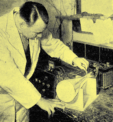
Checking over the apparatus ready for the reception of one of the BBC television transmissions.
The secret of good reception of television has now been discovered, but television has yet several years to go before it will have reached the same stage of perfection as radio.
So says Garry Allighan, the well-known radio journalist, in a recent issue of The Evening Standard, after he had witnessed a public demonstration of the PW television viewer, given by Messrs. Ediswan in Charing Cross Road, London. And he is right the secret of good television reception undoubtedly lies in the cathode-my method despite criticism which is levelled at it from a, certain untechnical quarter.
This criticism is particularly ridiculous in that it is levelled at the cathode tube not as a receiver of television but as a producer of X-rays or some similar harmful emanation.
We know little of the cathode tube, our critic is reported to have said - (we agree, he apparently does not know much about it) - and it is probable that the tube gives rise to rays that are definitely harmful. The cathode-ray system of television is a risky process, etc., etc.
I am not going to go deeply into the technical answer here. Dr Roberts, who has d.one a great deal of cathode and X-ray work, is fully discussing the question in a later issue of Popular Wireless, but I should like to assure readers that there is absolutely no cause for alarm at such ill-founded criticism.
There is Nothing Harmful
The cathode-ray tube is a soft tube, and what X-rays it might manage to emit with high-voltage operation are so soft as to fail to pierce even a few inches of air, let alone have the slightest effect on the human system or eyes. Probably the average luminous watch is far more risky a companion, and no one questions the wisdom or otherwise of wearing that popular adornment.
Probably one of the factors that has had most to do with the birth of this silly rumour is the fact that the light emitted from the cathode tube is not only apparently highly actinic and ultra violet in character, but that it spreads over such a wide surface, and therefore must, so it seems, cause powerful radiations.
That it is not highly actinic or ultra violet in character is proved by the fact that to photograph the cathode ray fluorescence We need ultra rapid panchromatic plates, and even then exposures of half a second or more are necessary for anything like a result. Ordinary plates are unaffected by this 'ultra violet' light with any exposure under a matter of many minutes.
Persistence
As regards the luminosity. This is a feature of persistence of vision, for the cause of the apparently continuous brightly illumined area is a small spot having a diameter of slightly more than a pin's head (not a hat-pin, Mr Critic - an ordinary pin), a fraction of the size of a luminous watch's second hand, but this rushes about so rapidly that it gives the appearance of at bright patch some inches in length and about 1¾ inches in width.
This you will be able to see for yourselves when you have completed. the assembly of the television viewing apparatus quite a simple matter, though it looks complicated.
I must make it clear at this point that, though I am about to describe the assembly of the cathode ray apparatus in what might be termed 'bench' form, it is not intended that the apparatus be permanently left in that manner.
After the first tests have been completed. the operating details being given next week, we shall describe the construction of an easily-made, but handsome cabinet, in which the whole of the gear can be housed, making the cathode ray television viewer a complete, household instrument.
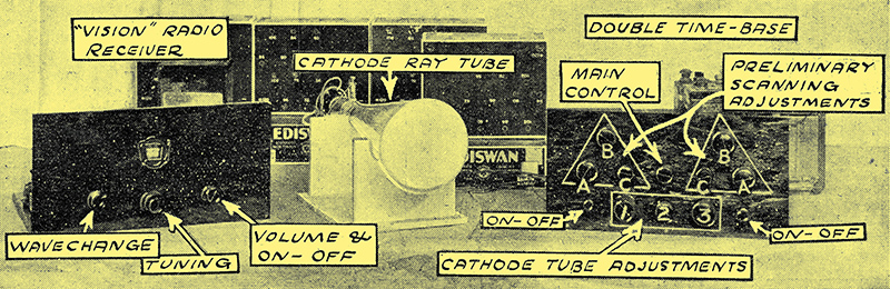
The construction of the double time-base and the vision radio receiver has been described, and all we now require in addition are the cathode tube itself (Ediswan type T), a wooden carrier, which can be knocked up in no time, an ammeter reading to 2 or 3 Amps. (A Sifam model is OK, and this will do for the final cabinet to be described later), and, if possible, though it is not essential, a micro-ammeter reading to 100 or 250 μA.
As regards HT, I should start off with about 400-450 Volts for the cathode tube, increasing it to 700 or so when you have got it working. The higher voltage is a great advantage in the increase of picture modulation and brilliancy it gives, but until you are used to working the outfit you may feel happier with less.
Small Capacity HT Cells
The HT and the various bias batteries can be made up of the smallest capacity HT batteries available - there is no need to use super or double-capacity cells. The only place where a good battery is required is that used for the vision receiver, and for the operation of the time-base. This battery can be common if desired, though for experimental purposes you may prefer to use separate batteries.
This assembly being in the nature of a try-out assembly, no provision is made for battery switching other than that already incorporated on the receiver and time-base for disconnecting the bias potentiometer connections and switching of the cathode tube filament. In the final cabinet model proper switches will be employed to take care of this necessary operation.
A Battery Box
For experimental purposes it is a good plan to rig up a box for the main HT supply (to the cathode-ray tube) so that it can be switched off readily and will be out of the way of stray pieces of wire or unauthorised and inquisitive hands. Such a box with a suitable lid, and carrying on it the control switch and a small fuse (60 mA or less) will be a decidedly useful aid to the tests you will have to carry out prior to finally housing the receiver in its special cabinet.
It cannot be too strongly stressed that the testing of a piece of scientific apparatus, such as this viewer, cannot be undertaken in at hurry. or a slap-dash manner. It must be carried out properly, and with due regard to careful arrangement of the interconnecting leads, all of which should be made of good rubber-covered flex.
Connections Made With Flex
Apart from short-circuits anywhere, the slightest leakage between certain parts or connections may result in failure to get the viewer working properly, while a disconnection may result in a blow-out of the cathode-ray tube.
So use good flex, free from whiskers, and go slowly over each connection, checking it with our diagram and with your set and time-base wiring, and making every connection rock firm.
This latter feature is most important, for we do not want any of the leads to come off, or to make uncertain contact. As a matter of fact, failure to make contact in the bias supply leads to the cathode-ray tube shield may result in serious damage to the filament of the tube.
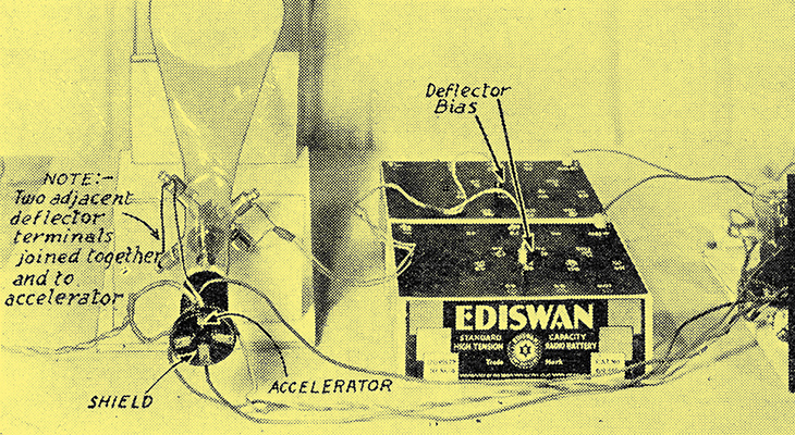
Two of the adjacent deflector terminals are joined together and connected to the accelerator, while the remaining two deflectors are taken direct to two separate bias batteries as shown in this photograph.
Note that two adjacent deflector terminals on the tube (going to different sets of plates) are joined together and taken also to the anode pin of the tube (the accelerator terminal). It does not matter at first which pair of deflector terminals is chosen as long as they are adjacent. we shall find by experiment if the ones chosen are the most suitable.
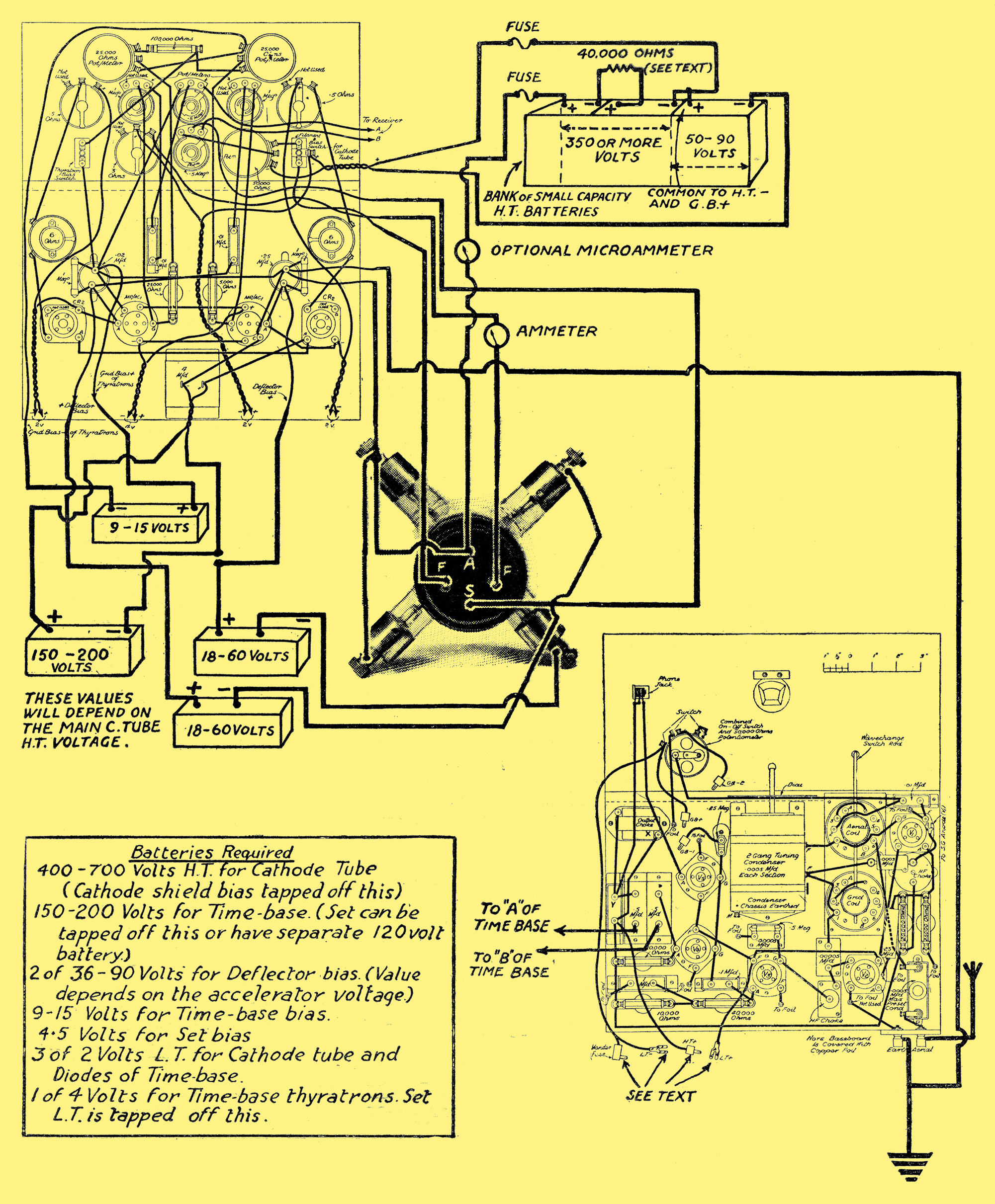
The bias for the shield of the cathode ray tube - a matter of between 50 and 75 Volts (for voltage of 350-700 HT) is tapped in at the end of the HT supply. In other words you can supply, say, 400 Volts HT for the tube's accelerator by means of four 120 Volt batteries in series, the last battery being used for HT and bias, the negative LT plug being the bias plus.
The Tube Works Like a Valve
This scheme is optional to the separate bias battery method. It does not matter how the bias is obtained provided it is reliably applied - there must be no loose or risky plug contact anywhere.
As regards its operation, the cathode ray tube can be regarded in the light of an ordinary three-electrode valve i.e. the variations of voltage on its grid (shield) modulate the electron stream. but it is not so robust to minor hardships as the thermionic valve, and so must be treated more circumspectly.
The normal valve does not suffer serious damage if the bias is momentarily removed, though that is a practice that cannot too strongly be condemned. The cathode tube is in great danger if such a circumstance occurs, for on removing the bias (HT and LT being on), all focusing of the electron stream is stopped and the electron current rises tremendously.
Resistance To Protect Filament
The result is a very great strain on the cathode, which is really a sort of hot point at the tip of the filament rather than the whole filament, and such an electron surge causes lumps of the emissive material to be torn oft, the mechanical tearing being strong enough in some cases to fracture the filament. So take care you never remove the bias while the tube is 'on'.
There is a way of minimising the risk by placing a resistance in the HT feed (a convenient place is in the coupling between two of the centre blocks of 120 Volts), so that the rise of accelerator current is kept somewhat in check. A resistance of 40,000 Ω is a useful value, and this, while not affecting the operation of the tube, will to some extent safeguard the tube against sudden surges.
The radio viewer can take its HT from one of the two cells used for the time-base 4 Volt supply, the negative LT of the set being common with the negative LT on the 4 Volt battery. It must be remembered in this television viewer that the accelerator and two deflectors of the tube are at earth potential, by virtue of the connections via the time-base and the set. They are also 400 or so Volts above the shield, and at HT voltage to the filament and filament battery of the cathode tube and two of the deflectors.
This is important, for it is so usual to have every HT point in a radio set above earth potential, that the use of points at earth potential and yet above other points may at first be difficult to realise. The result is, of course, that the filament, two deflectors and shield of the cathode tube are at HT below earth. This should strongly be borne in mind.
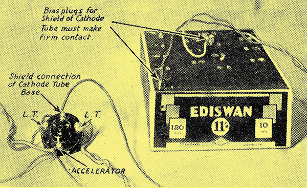
The cathode ray tube fits into an ordinary four-pin valve holder, the connections to which are indicated above. As in other parts of the circuit, it is of the utmost importance that these connections should be securely made.
The connections to the filament, accelerator and shield of the cathode tube are carried out by an ordinary four-pin valve holder, as shown in the photograph. In the wiring diagram, however, we show the connections going straight to the tube base pins. As in the ordinary valve, the filament and anode pins are used for filament and anode (or accelerator), and the grid pin is for the modulation. controlling electrode, the shield (corresponding in effect to the grid of a valve).
Connections to Deflectors
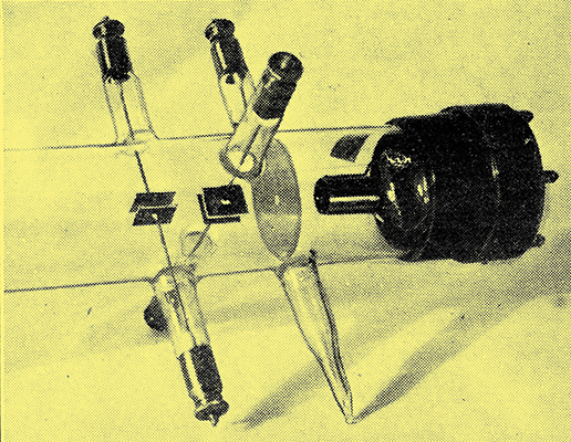
An illustration of an experimental cathode ray television tube which gives a very clear idea of the relative positions of the cathode shield, the accelerator (note the hole through which the electron stream passes), and the two pairs of deflector plates. The connection to the accelerator in this case is made on the side of the tube instead of to an anode pin as in the Ediswan T tube used by PW.
The last cathode tube we used in our experiments, and illustrated here, has the connections to the deflectors coming out through glass horns some way down the tube from the Bakelite base. The final Ediswan type T tube, however, has, I believe, the deflector leads taken along inside the glass, to the base, which is a little wider. Here they are brought out to four large terminals.
Their relative positions correspond exactly with those on our tube, and the connections to adjacent terminals and to the accelerator, as shown in the link-up diagram, are exactly the same. It is only the appearance of the tube that has been altered somewhat.
When connecting up the two 2 Volt LT batteries for the diodes on the time-base, make sure that the batteries do not touch each other. This seems ridiculous, I know, but we have found that in many instances there can be sufficient leakage between these two cells, via the surfaces of the containers, to upset completely the operation of the time-base.
After all, the cells are connected via the diode filaments to the anodes of the thyratrons and to the 0.25 and 0.02 μF capacitors respectively, so that leakage between the two circuits would naturally upset the control of the HT supply to the capacitors.
Carefully Check the Wiring

This comprehensive diagram shows exactly how the complete viewer is wired. The relationship of the various sections is clearly indicated, and a list of all the batteries required included. The two meters are used to indicate the filament and accelerator currents of the cathode tube, the ammeter being an essential part of the system, while the micro-ammeter though advantageous is by no means indispensable.
Such an effect is obvious when you have it pointed out to you, but in practice it is easy to let the glass containers of the two LT cells touch without realisation of the fact that it is just that touching that is throwing out the timing of the thyratron flashes.
With the whole apparatus connected up in accordance with the diagram, and with voltages available as suggested in the article and the diagram, I am going to ask you to wait till next week before you switch on and commence your television reception. In the meantime, check over every connection again and again, making sure that everything is not only correctly connected, but is connected firmly with no possibility of coming undone.
Return to series start
|