|
This week we round off the description of the construction of the Popular Wireless Cathode-Ray Television Viewer with details of the cabinet. This enables the various units to be combined into a neat and compact instrument.
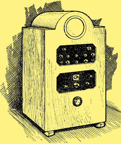
A sketch of the completed cabinet with the tube and units in place.
The special cabinet to house the television gear presented a new problem, for it necessitated designing something different from any type of cabinet hitherto constructed. The resultant cabinet is, however, both pleasing and sufficiently substantial to withstand the weight of the 700 Volts HT contained in the tray at the bottom of the cabinet.
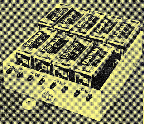
The 120 Volt: batteries are placed on their sides in a special battery drawer, which carries terminals and a switch.
The framework for the cabinet may appear to be rather fragile, but when the necessary crosspieces and shelves are in position the cabinet as a whole is remarkably rigid.
The construction of the cabinet should be commenced by cutting the four pieces for the base; these are two pieces 6 in × 18½ in × 1 in one piece 6 in × 17½ in × 1 in, and the remaining section, i.e. for the back, 2 in × 17½ in × 1 in.
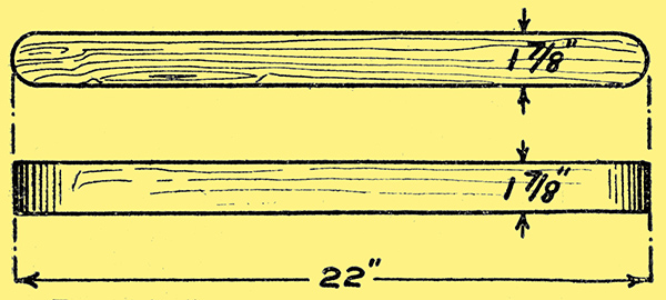
Two plain 'runners' are used instead of four separate feet.
To the inner face of each piece of wood nail a strip centrally 10 in × 1½ in × 1 in, with one edge in each case flush with the bottom edge of the above four pieces.
Fixing the Feet
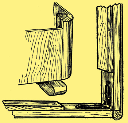
Metal brackets strengthen the corners while a moulding improves appearance where the sides join the front or back.
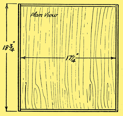
The lower baseboard of ⅜ in ply, on which the HT battery drawer rests, is now nailed to the four sides, resting on the pieces of wood already nailed to the side pieces. Details of the corners are shown above.
Now fix the 3 in × 3 in or 3 in × 4 in brackets into position as shown, carrying this work out before the corner supports are fitted into position.
It may seem rather strange so early in the construction to fit the feet, but it must be borne in mind that the domed top prevents the cabinet from being turned on its end.
The feet are cut and shaped to the dimensions given and then fixed. by means of 3 in. No. 8 countersunk wood screws to the front and back of the main bottom framework, which is already complete.
The four corner supports are out from 1 in × 1 in flush corner moulding - Handicrafts K343. Other suitable mouldings are available from the above manufacturers, including an octagonal corner moulding. Having out the four pieces to the correct length, they may new be fitted into the base framework already constructed. It is not necessary to screw those corner supports into position; 2 in oval nails are quite satisfactory.
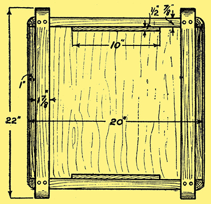
A 'worm's-eye-view' diagram that shows the fitting of the runners and other important details.
Temporary pieces of wood must now be cut and fitted to the top of the four corner mouldings so as to keep the sides and front pieces the correct distances apart during the process of fitting the four crosspieces, which carry the top and middle shelves.
In the case of the top shelf, slightly wider and thicker wood is used than for the lower shelf, thus further strengthening the framework at the point where the corner supports are likely to buckle. These two pieces are 18½ in × 4 in × 1 in.
In the case of the lower shelf the side supports are arranged inside the corner supports so as to facilitate the removal of the rear half of this shelf which rests on these two supports.
Making the Shelves
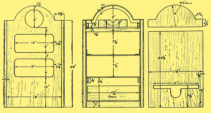
The diagrams show all the main dimensions of the cabinet. From left to right, they are: the front, the interior disposition and the back pieces.
It is advisable at this stage to fix the side pieces for both shelves and also the ⅜ in plywood shelves temporarily into position.
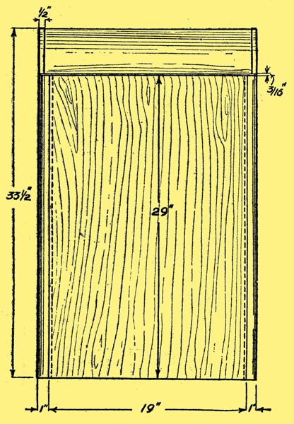
Side elevation.
Each shelf should be made in two pieces so as to facilitate fitting and arranged that when the front half is level with the main part of the two front corner supports, and the back halves are flush with the main part of the rear corner supports, there is a gap between each section of the shelf of ½ in. or so. This allows for bringing leads down through each section of the cabinet to the section below or above.
Two brackets must now be fitted between the top shelf and the back corner supports in case the corner should pull away from the shelf supports and shelf.
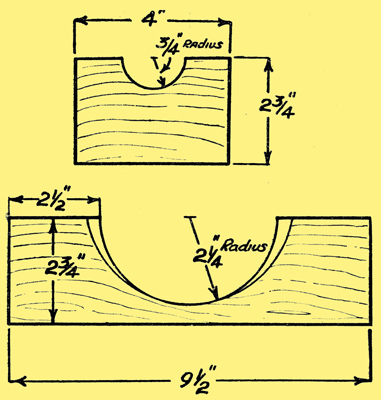
The tube itself rests upon two wooden supports cut out as above.
The carrier for the cathode tube should now be constructed to the dimensions given, and it will be seen from the sketches that the front carrier is chamfered so as to give a good seating for the tube.
The two halves of the carrier are nailed to two strips of ⅜ in ply ready for fixing to the underside of the final two topmost side supports of the framework; these pieces are 19⅝in × 3 in × 1 in. Actually these two top pieces are arranged to come centrally inside the corner supports, but are not nailed between in the case of the top shelf support.
The sections for the shelves should now be fitted into position with the exception of the back half of the lower shelf which is to carry the accumulators.
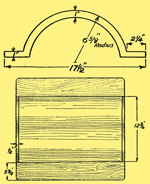
The top of the cabinet is provided with a domed piece, as indicated here, which covers the cathode-ray tube.
The next operation is to cut and fit the three bridge pieces which support the domed top of the cabinet, and it is essential that these are out and fitted with great care if the dome is to be free from 'bumps'.
In the case of the centre arch it will be necessary to out the top side supports so as to allow the bridge end to come flush with the top edge of these two supports. The back and front arch ends fit into the space left between the ends of the side supports and the edge of the corner moulding.
The skeleton framework should now be quite rigid, and must be examined to make quite sure that this is so; if not, then an extra nail or screw or another bracket will do the trick.
Until the arches are in position it is advisable not to remove the temporary pieces of wood referred to above; in any case the back piece should not be removed until the 18 in × 2 in × ⅝in strut is fitted between the two back corner supports and the brackets are in position.
Now for the fitting of the actual dome, which consists of 1½ mm birch bending ply, for it may be bent dry, obviating the need for steaming. The dome panel should be cut to the correct width, 20¾ in., and also to the correct length. Due, however. to slight errors, differences in the thickness of the wood, etc., the actual length has been purposely omitted. It can, however, be easily taken by means of a piece of string or a flexible steel rule. It would also be advisable to check the distance between the outside arches before cutting. The above material is quite easily cut with scissors or a razor blade, since it is only 1½ mm thick.
Completing the Top
The ply is held in position by means of ½ in veneer pins, although a little glue is an advantage. To make quite sure that there are no 'bumps', the ply should first be nailed to the centre of the arches and then marked down to the base of the arches.
Two ½ in wide strips of the above 1½mm ply are glued over the front and back edges to prevent splitting. Two top panels of 4 mm ply are now out to fit between the edge of the dome and the extremity of the sides, i.e. including the rebate of the corner moulding. And do not forget to chamfer the edges of the panels where these meet the dome.
There are several types and classes of plywood which can be used for the front, sides and back; but whether this is faced ply or solid it is essential that the thickness should be only 4 mm otherwise the ply will not fit snugly into the grooves of the corner moulding.
Before actually cutting the front and sides make quite certain that your particular dimensions in regard to height and width agree with those given for the various parts, since only a slight difference in the making of the skeleton will have resulted in a different height or width for the panels. The door of 4 mm ply at the rear of the cabinet is in two pieces, both of which are held in position by small leaf buttons.
Hinges are hardly necessary
The front and side panels are now fixed into position by means of ⅝ in veneer pins. These pins are also used to fix the side and front panels to the various side, crosspieces, etc., thus preventing 'bulging' at the centre of the panels.
The size and construction of the battery drawer is illustrated in this diagram.
My understanding of such woodworking in the 1930's and beyond is that nailing a cabinet together was 'just not done'. Joints and hot animal glue would have been the fixing methods of choice - ed.
Return to series start
|