|
In this article are described some of the results of experiments carried out with a valve specially designed and constructed to facilitate observation of the paths taken by electron beams in valves of the ordinary type.
In almost any descriptive account of the cathode-ray oscillograph one may expect to find a number of terms which, though they are applied to electrons, have been taken over with hardly any change of meaning from the apparently quite different subject of optics. Thus, there will be a reference to a beam of electrons, and discussion of focusing, of images, and so on. More recently still we have heard t of electron microscopes and of electron lenses, all implying that in the field of electronics there are processes analogous to those of optics, with rays or beams of electrons behaving similarly to rays of light.
There is, indeed, a very close analogy, arising from the fact that free electrons in a vacuum (such as the electrons emitted by the filament into the space inside a valve) tend to move along the lines of electric force in the space in which they find themselves. Another way of saying the same thing is that they tend to move perpendicular to the equipotential lines (or surfaces) of the electric field. This may sound like advanced theory, but the idea is really quite a simple one. An equipotential line is no more than a kind of electrical. contour line, similar to those one is accustomed to see on a contour map, and just as, in a contour map, the contours are lines joining points which lie at the same height above sea-level, so, in an electric field, the equipotential lines, or , electrical contours, are lines joining points which are at the same potential, or electrical height. One knows that on a contour map the contour lines crowd together where the slope of the ground is steepest, as illustrated in Fig. 1.
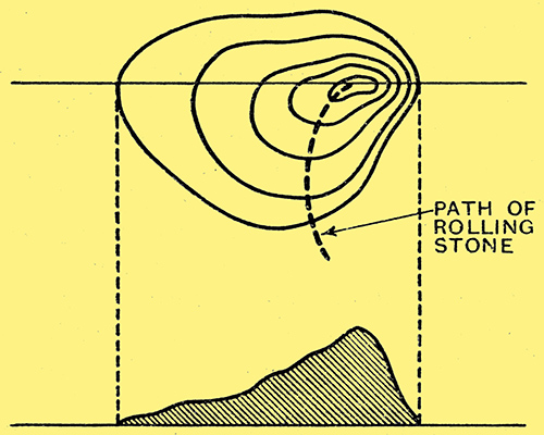
Fig. 1. - A geographical analogy; showing a family of contours illustrating the tendency of a rolling-stone to run perpendicular to the contour lines.
One also knows that if a round pebble is allowed to roll freely on a hill, such as that shown in Fig. 1, it will, whatever direction it may have initially, tend to take the shortest and steepest way down. It will tend, that is to say, to take the shortest route from one contour to the next, and this shortest route is, of course, the line perpendicular to the contours. Such a route is shown dotted in Fig. 1. Similarly, a free electron, whatever its initial direction of motion, will tend to be deflected in a, direction more nearly perpendicular to the electrical contours or equipotentials of the electrical field.
Electrical Contour Lines
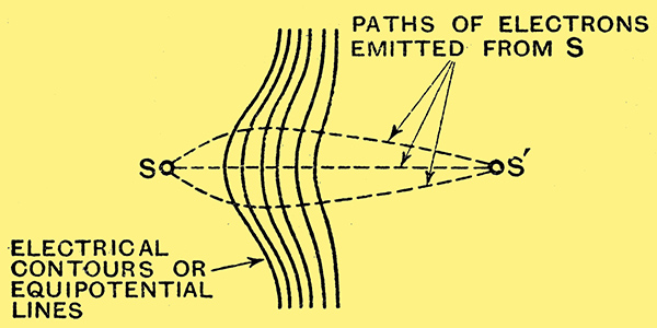
Fig. 2. - Focusing effect of curved equipotential lines.
Suppose, for: example, that the point S in Fig. 2 is a source of electrons, and that potentials are applied to certain electrodes in the vicinity in such a way as to produce an electric field of which the equipotentials, or contour lines, are as shown in the figure; then electrons emitted from S will follow curved (paths similar to those shown dotted, and in certain cases may even be definitely focused on a point such as S'. This, rather crudely portrayed, is the essential mechanism of the so-called electron-microscope. If the electrons emitted from S are made to converge on some sort of fluorescent screen at S', then the latter will show an enlarged image of the source. Briefly, curved equipotential surfaces bend or refract beams of electrons in much the same way that the curved surfaces of glass lenses refract rays of light.
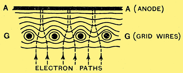
Fig. 3. - Electrical contours of grid-anode space in an ordinary valve, showing formation of electron beams.
Now consider the configuration of the electric field in, say, a triode valve. In Fig. 3 let the line AA represent a section of the anode, and the line of black circles GG represent sections of the grid wires. With a high potential on the anode and a low or zero potential on the grid, the contours of the electric field (not the lines of electric force, but lines everywhere perpendicular to the lines of electric torce) will be somewhat as shown in the figure. The curved lines in the grid spaces can be thought of as sections of cylindrical lenses, which will tend to break up the stream of electrons travelling towards the anode into a number of separate streams or bundles, more or less convergent, depending upon the actual potentials of the electrodes. Such streams may or may not be actually focused on the anode, but it is clear that in any case there will be a tendency for the electron current-distribution over the anode to be, not uniform, as is usually assumed in simple descriptions of the operation of the valve, but non-uniform, possibly even discontinuous, with separate patches or strips corresponding to the separate meshes or strip-shaped spaces of the grid. So much might be expected on general qualitative grounds, but there would still be uncertainty as to whether the actual electron velocities and the field curvatures would in practice be such as to produce any very marked breaking up of the initial uniform electron stream. The actual electrode system is too complicated to permit of any exact and convincing theoretical analysis, and it is therefore very satisfactory to have a clear, positive, and visible demonstration of this effect, such as that produced by M Knoll and J Schloemilch, of the Telefunken Gesellschaft, and described by them in the Arclziv für Elektrotechnik.
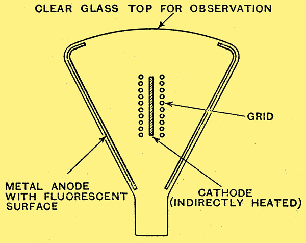
Fig. 4. - Sectional schematic diagram of triode valve for observation of electron beams.
In order that the effect, if it existed, could be observed visually, a very special valve was constructed in the form shown in Fig. 4. The sloping sides of the funnel-shaped glass container were metallised and used as the anode, and a thin film of fluorescent material was deposited on this anode, in order that the impingement of electrons might give rise to patches or areas of light which could be observed from above through the clear glass top.
Interrupted Electron Stream
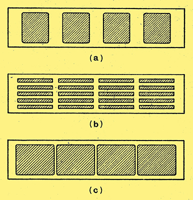
Fig. 5. - Types of fluorescent patterns produced on the anode by electron beams. Sketches based on photographs by Knoll and Schloemilch; the anode is assumed to be cylindrical and opened out flat to show the patterns.
It was found that the electron stream was, in fact, broken up by the various lenses of the grid structure, and that the anode fluorescence was, in consequence, patchy or striated. A variety of patterns was produced, depending upon the relation between the grid and anode voltages. Some of these patterns are shown in Figs. 5a, b, and c, the shaded patches representing areas of fluorescence on the anode. (The vertical gaps between the shaded patches shown in these figures were due to the four stout wires used to support the spiral grid winding. The gaps are not exactly electron shadows of the supporting wires, for the width of the gaps was found to vary considerably in the different patterns. In one case, when the main segments of fluorescence were made to overlap at their sides, the gaps were actually transformed into lines of brighter fluorescence.)
The observed variety of pattern obviously arises from variation of the effective focal lengths of the individual cylindrical lenses of the grid structure. Each such lens will tend to produce its own more or less convergent beam of electrons, which may be focused on, in front of, or behind, the anode, depending upon the electrode potentials. Except where the beams are focused, there will, of course, be a certain overlapping of the beams. Thus, Fig. 5b shows a fairly sharply focused condition, but in Fig. 5c it would seem that the separate striations of Fig. 5b have been widened enough to overlap at the edges and give a more nearly uniform distribution.
The most significant of these patterns, from a practical point of view, is probably the striated form shown in Fig. 5b. On a continuous anode, such as was used in these experiments, the precise nature of the electron distribution will probably not produce any appreciable effect on the observed characteristics, but there are clearly possibilities of very pronounced effects on characteristics when the electron stream flows through another grid, as in the tetrode or screen-grid valve. Thus, for example, one would expect the effect of the second grid to depend considerably on whether its wires were in or between the separate electron beams formed by the first, or control, grid.
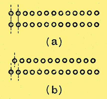
Fig. 6. - Alternative arrangement of grid wires in a double-grid valve.
This feature of the subject has not, of course, been overlooked. In a later publication M Knoll [★] Zeitschrift für Technische Physik, Dec., 1934. describes some measurements with tetrode valves of special construction in which the outer-grid wires were placed alternatively as shown in Figs. 6a and 6b, i.e., either in or between the planes of the inner-grid wires. He states that in the two configurations, the screen-grid currents differed by as much as ten to one, and the slopes by two to one.
This realisation of the occurrence, in ordinary valves, of a separate beam structure of the electron stream is of comparatively recent date, and its practical significance has not yet been fully explored. It is already clear, however, that it may be a very significant factor in operation and that it offers some interesting possibilities in design. Knoll points out, for example, that a cathode having cylindrical or cup-like recesses itself produces elementary beams, and that grid current can be minimised by locating the grid openings opposite to these recesses.
|