|
A gas-discharge valve with grid control.
The hot-cathode mercury vapour rectifying two-electrode valve has already appeared on the market in this country. When a grid is added the valve is called a Thyratron, and possesses some remarkable properties which are likely to find wide application in the future. By its use it is practicable to convert DC to AC, to transform DC to a higher or lower voltage, and, as larger sizes are developed, a new method of transmitting power at a high DC voltage becomes a possibility of the future.
The growing interest which is being shown both in this country and abroad in the various commercial applications of the gas discharge valve known as the Thyratron makes it appear that a short article dealing with the general principles and performance of this device may be acceptable.
The applications of the Thyratron in commercial spheres have undoubtedly been developed to a much greater extent in the United States of America than in this country, but its possibilities are so widespread, and some of its applications so important, that it may be safely forecast to be only a matter of time for similar demands to arise on this side of the Atlantic.
Fundamental Principles - Two-electrode Tube
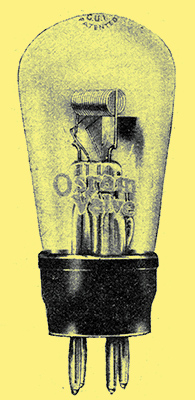
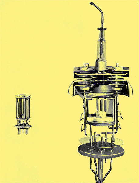
The GU1 Rectifier.
Let us consider first what are the fundamental principles underlying the action of the Thyratron. To do so it is of advantage to turn first to a study of the gas-filled rectifier, a type of which, in the form of a Hot Cathode Mercury Vapour Valve, has already appeared on the market in this country, an example of this being the GU1 Rectifier.
This valve consists of an electron-emitting oxide-coated helical cathode capable of a very considerable saturated emission current and a plate anode, the whole enclosed in an air-exhausted bulb in which a few drops of mercury have been introduced. The enclosed space therefore becomes filled with atoms of mercury vapour at low pressure.
On heating the cathode to the required temperature to emit electrons, and on applying a low positive voltage to the anode, a small anode current passes limited by the internal resistance, which is now comparable to that of a similar hard valve at very low anode voltages. Immediately the positive anode voltage is increased to about 15 or 20 Volts, however, the whole action of the valve is changed. At this voltage a much larger current equal to the full saturated current will now flow, owing to the ionisation of the atoms of mercury vapour by bombardment, the positive ions thus released going to neutralise the space charge. The anode volts will, however, remain at about 15 whatever the current taken up to the saturated emission. If higher voltages and no limiting resistance are used, the current will become excessive and the valve will be destroyed.
In this condition of ionisation the valve exhibits the blue glow typical of a mercury vapour discharge. It is important at this stage that the value of external resistance, or load, is sufficient to limit the anode current. As the internal resistance of the valve, as explained above, is very low, due to the neutralisation of the space charge, this anode-cathode voltage is maintained constant at about 15 Volts, and is practically independent of the load up to load currents which would cause excessive ionisation, bombardment of the filament by positive ions, and its consequent disintegration and destruction as a low temperature emitter.
The main advantage of the mercury vapour rectifier, therefore, is the greatly improved regulation when compared with the hard valve, due to its very low internal resistance with a constant voltage drop of about 15 Volts. This low anode voltage means less Watts in the anode, and to handle a given amount of power the bulb can be made very much smaller than with the hard thermionic rectifier.
The action of the grid in a three-electrode hard valve is well known, its function being to act as a continuous control to the flow of electrons between cathode and anode. Under normal operation conditions, however, the action of a grid placed in a mercury vapour discharge valve has an entirely different effect.
The Thyratron under normal working conditions may be broadly described as a Controlled Rectifier of the mercury-vapour type.
We saw that in the mercury vapour valve a small space current flows at very low anode voltages, i.e., voltages below which the discharge commences. The valve under such conditions may virtually be considered as a hard valve, and with the grid included, as in the Thyratron, the same control on this small space current is exerted as in a hard triode valve. This means that a negative voltage applied to the grid can suppress the anode current.
Now, if with a negative bias the anode voltage is gradually increased it will arrive at a certain value, depending upon the geometry and negative voltage of the grid, at which, as in an ordinary three-electrode valve, the anode begins to take a small current. At this point, if the anode voltage is at least 15, the discharge commences, and once it has done so the grid exercises no further control on the anode current. The value of anode voltage at which the discharge will commence is equal to the amplification factor of the Thyratron multiplied by the negative grid voltage applied. For a given design the larger the negative grid voltage the higher will be the anode voltage required to start the discharge. It is not now possible to stop the anode current, no matter how much negative voltage is put on the grid, and this would continue to flow indefinitely until the anode positive voltage is removed or reduced below 15.
As with the two-electrode mercury vapour rectifier, while the discharge is in progress the resistance is extremely low and the anode voltage maintained at about 15 Volts. It will be seen, therefore, from the above brief description of the Thyratron action that the grid, by the choice of its geometry and its relation to the rest of the electrodes, and by its negative voltage, can be made to act as a trigger by which the anode current can be started on the anode voltage arriving at a specified figure, but once started the grid exercises no further control.
Some Applications
The applications of Thyratrons open up wide and fascinating possibilities, and may be broadly divided into two classes - those with AC applied to the anode, and those with DC Let us consider the AC class first.
AC applied to the Anode and DC Grid Control
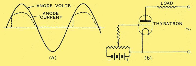
Fig. 1. - (a) The waveform produced with AC on the anode and DC on the grid. (b) Simple grid control circuits.
To consider the performance of a Thyratron with AC on the anode, turn to Fig. 1, which indicates the anode Volts waveform due to the AC applied to the anode. As we saw above, the negative grid voltage can be fixed at a critical value so that the discharge will commence at any given anode voltage above 15. We can thus by means of a small potentiometer in the grid circuit arrange the grid voltage so that as the anode volts rise during the positive half-cycle of the AC wave the grid will cease to hold the anode current in check at any point of the rising voltage up to the maximum in the half-cycle.
On the anode voltage falling to zero again the anode current will cease, and the grid will once more exercise control and prevent the discharge commencing until the anode voltage has reached a similar point on the next position half-cycle. During the negative half-cycle no anode current can flow. By means of a very small control in the grid circuit, therefore, we can arrange things so that any required degree from the maximum rectified current to half this value may flow through the load. Thus, considerable load currents may be controlled by a small knob.
AC Grid Control
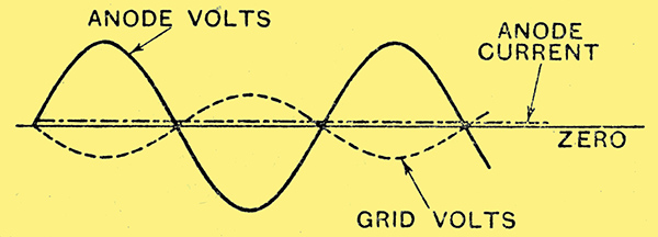
Fig. 2. - The grid volts 180° out of phase with the anode volts.
The disadvantage of the above DC grid control is that the anode current can only be cut down to half-value. A better method is to utilise phase differences in anode and grid voltages. Now let us refer to the diagram of the anode voltage wave shown in Fig. 2. By making the grid volts 180° out of phase with the anode volts the grid voltage will gradually become more negative as the anode becomes mo:re positive, so that the grid exercises complete control throughout the positive half-cycle, no discharge can take place and no anode current can flow. This is providing the anode voltage does not exceed the amplification factor of the Thyratron multiplied by its grid voltage.
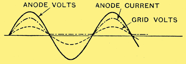
Fig. 3. - The grid volts arranged to be in phase with the anode volts.
In Fig. 3 the grid volts are shown in phase with the anode volts, and it will be seen here that the grid permits current to flow during practically the whole of the positive half-cycle. Referring to Figs. 2, 3, and 4, it will be seen that by a continuous control on the phase difference between anode and grid voltage any proportion of the maximum anode current can be made to pass from complete cut-out to maximum current.
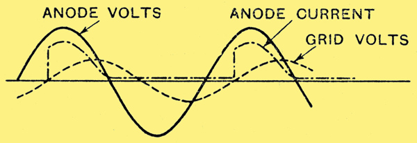
Fig. 4.- Where the grid volts and anode volts are 90° out of phase.
This is of particular utility in all light-dimming circuits, and is undoubtedly an important application of the Thyratron under the AC condition. Compared with the resistance dimmer the Thyratron may be said to have the advantage that it has no moving parts carrying load current, it is of high efficiency, there is very little heat to be dissipated, connections are electrical rather than mechanical, and a small space only is required for the control.
DC applied to the Anode
With DC on the anode the Thyratron can be used to record events such as transient voltages. As we have seen, the anode and grid voltages can be so adjusted that the grid will act as a very delicate trigger and start up the anode current at any desired point. Once started, it will continue to flow until the anode voltage is removed. The general method of stopping current in a DC operated Thyratron is to make the anode negative for an instant. During this instant the ions diffuse away from the grid, thus restoring grid control.
Application as a Relay
The action is similar to that we, have described for the AC anode voltage condition except that the discharge will continue instead of ceasing and restoring grid control under AC conditions.
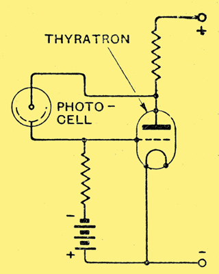
Fig. 5. - An interesting application of the Thyratron where a photo-cell is made to act as a grid potentiometer.
A particular application shown in Fig. 5 is utilisation of a photo cell as the grid potentiometer. When light falls on the photo cell its resistance falls, and the circuit can be so arranged that the grid of the Thyratron attains a positive potential. This enables the discharge to commence and the load current to flow. A permanent negative voltage is applied to the grid so that before light falls on the photo cell this negative charge prevents the start of the glow.
Inverter Circuits DC to AC
Let us consider the case of a Thyratron in a simple trigger circuit, where a switch is used to make the anode negative for an instant and thus restore grid, control after discharge.
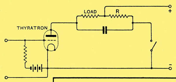
Fig. 6. - A trigger circuit using a switch to make the anode momentarily negative.
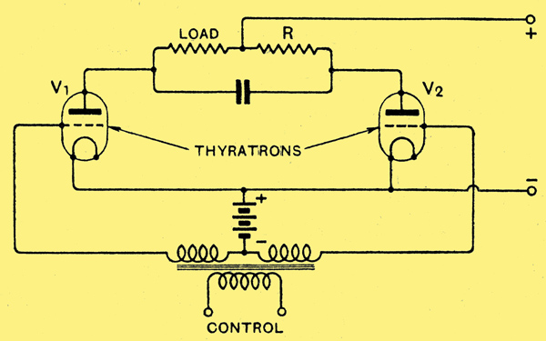
Fig. 7. - By employing a second Thyratron instead of a switch of Fig. 6 a circuit for transforming DC to AC results.
Instead of a switch it is possible to use a second Thyratron, see Figs. 6 and 7. Making the grid of Thyratron V2 positive is equivalent to closing the switch in the previous case. In this way the current is transferred from Thyratron V1 to V2. By means of a small subsidiary AC control it is possible to reverse the position of things and make the grid of Thyratron V1 positive. Thus, the current may be transferred back again to Thyratron V1.
Now, instead of the load resistance R, substitute the primary of a transformer. In the way just described the small subsidiary AC grid control can now be made to divert the heavy DC anode current first from one Thyratron to another, thus setting up what is equivalent to an AC voltage across the primary of the transformer. This AC voltage may be transferred to a suitable secondary winding, and we have thus the phenomenon of DC input being transformed into AC output. This method utilises a small independent AC source to determine the frequency of the resultant AC voltage and actuate the grid voltages as required.
It is possible, however, by connecting a tuned circuit between the two anodes to make such an inverter operate at any frequency determined by the tuned circuit.
One of the great advantages of the use of Thyratrons for this purpose is that only 15 Volts out of the total supply available is used up across the valve. The use of hard valves in such circuits would be rendered impracticable due to their high internal resistance.
For high voltages the efficiency of the Thyratron as an inverter may be higher than 99%. The higher the voltage the greater the efficiency, and at 10,000 Volts the efficiency is as high as 99.85%. Allowing for cathode heating Watts at 60 Watts per ampere output, the overall efficiency is 99.25%. The efficiency of a mechanical converter cannot attain such figures.
DC Transformer
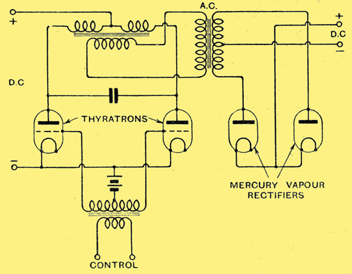
Fig. 8. - The use of two-electrode mercury vapour rectifiers in conjunction with Thyratrons renders it possible to make a DC transformer which has no moving parts.
By combining the properties of the Thyratron in an inverter circuit such as described above, and the mercury vapour rectifier, it will be seen how it is easily possible to transform direct current of one voltage into direct current of any other voltage desired, thus effecting a DC transformer (Fig. 8). Such a DC transformer may be said to have many advantages over rotary converters, such as absence of moving parts, small bulk, and ready replaceability of any defective part.
Power Transmission
The reason why alternating current has been employed up to the present for long-distance power transmission is undoubtedly the ease with which its voltage may be transformed at either terminal of the line, and, therefore, its extreme flexibility operation. It is well known, however, that the transmission of AC power offers several serious disadvantages compared with DC Thus, for a line designed to carry a given AC voltage RMS, the permissible DC voltage along such a line would be √2 times this, or a line designed for 132,000 Volts AC peak would safely carry 186,000 Volts DC.
Also, with AC transmission, the power factor of the line is a most important feature, and calls for considerable additional compensating machinery involving great cost. With DC transmission such power factor compensation is avoided. The possibilities of DC transmission of power are fascinating, and the whole subject is one of intense interest to all electrical engineers.
The principle of the Thyratron is proved - it remains for the development of the principle to provide Thyratrons with increasingly greater power-handling capacities, as the practical utility of this device would appear only to be limited by the volt-amperes it is capable of handling.
As at present known, no Thyratrons have been made to stand above 20,000 Volts pressure. If Thyratrons could be made to withstand voltages of the order of 100,000 they immediately become of the greatest interest for DC power transmission - undoubtedly one of the most far-reaching applications of this latest addition to the thermionic-valve family.
|