|
The latest series of Cossor AC valves contains some twelve different types in all, and while a few are identified by the same type numbers as a year or so ago, their characteristics are widely different. As an example we need cite but two as typical of the substantial improvements effected. In the 1930 series the 41MP had an AC resistance of 5 kΩ, an amplification factor of 13, and a mutual conductance of 2.6 mA. per Volt. It provided an undistorted output of about 260 mW. The latest version of this valve has a mutual conductance of 7.5 mA. per Volt, and the amplification factor has soared to the exceptionally high figure for a power valve of 18.7. That the valve falls within this category is exemplified by the power output figures, which are given as 1,250 mW.
The 41MXP is another outstanding example, as, having the same mutual conductance as the 41MP, it gives some 2 W output and has an amplification factor of 11.2. Both of these valves give their respective power outputs with quite modest input voltages, so that they can follow immediately after the detector and be coupled to it by a transformer affording a 1:3 or 1:3½ step-up ratio.
The correct operating voltages for the 41MP are -7.5 Volts grid bias, with 200 Volts on the anode, while the 41MXP requires -12 Volts grid bias with the same anode potential. In a practical case these voltages will be derived by the potential drop across the ends of a resistance connected between the cathode and the main HT negative, with suitable decoupling in the grid return lead from the secondary of the LF transformer, as shown in Fig. 1.
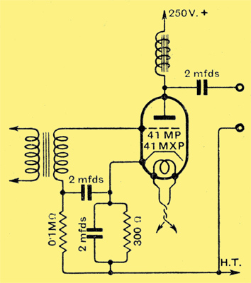
Fig. 1. - Typical circuit arrangement for output stage showing grid decoupling and bias resistance.
It is interesting to record that the same value of bias resistance would seem to serve for either the 41MP or the 41MXP, which may be intentional on the part of the designers or come about by a happy chain of circumstances; we prefer to accept the former as the explanation. Be this as it may, the fact remains that the one valve can be removed and its larger brother substituted should an increase be desired in the power output. This may be achieved without modification to the circuit, provided there is sufficient latitude in the HT supply to make up the difference between 24 mA. and 40 mA, which are the respective anode currents for these two valves.
The Detector
For the detector stage preference might be given to the 41MH valve, although under certain conditions the 41MHL could be employed. Any of the three recognised methods of detection can be used, but as the power grid arrangement is now one of the most popular a suitable circuit would be as shown in Fig. 2.

Fig. 2. - Connections for power grid detector showing one method of including a gramophone pick-up.
A suggested method of arranging for gramophone reproduction is included in the circuit, and suitable values are included for the components, assuming an 'A' type rectifier is employed giving 250 Volts DC on the full load. Where a higher voltage is available the 300 Henry choke could be replaced by a resistance of not less than 30 kΩ. In the space available it is impossible to deal with all the valves in this series, but before concluding mention must be made of two special types, namely, the MS/PenA. and the 41MDG. Although the first mentioned is a pentode in that it has five electrodes, its function is that of an amplifier, and consequently falls in the same category as the screen-grid tetrode. Its particular features are that it will accept a large input voltage and that the grid volts-anode current characteristic is much more linear than the usual SG valve. In addition to its claims as an HF amplifier, it offers possibilities as a detector, especially of the power grid variety, the circuit for which is shown in Fig. 3.
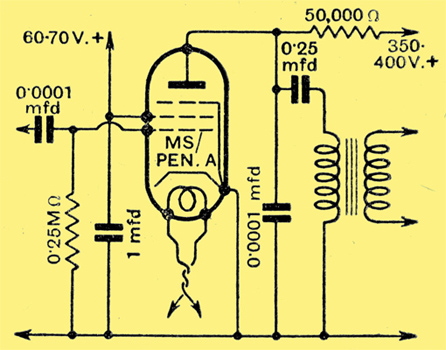
Fig 3. - Special high impedance pentode used as a power grid detector.
The 41MDG is a bi-grid [★] This is a tetrode and not the space-charge bi-grid of the early 1920s-ed. valve developed as a combined detector and oscillator in supersonic heterodyne receivers, a typical circuit, together with suggested values for the necessary components, being illustrated in Fig, 4.
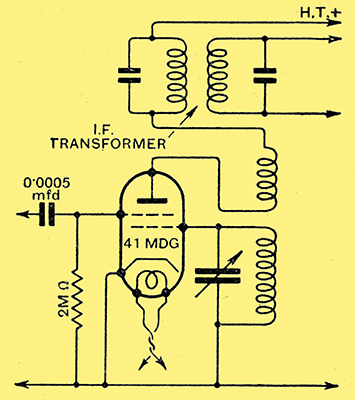
Fig. 4. - Circuit connections for a single-valve frequency changer in a superhet using a bi-grid valve.
Tests have been made with various specimens of the new series of AC valves, and their performances were highly satisfactory, being fully in keeping with the exceptionally good characteristics exhibited by these valves. In no case did we find the slightest trace of reversed grid current, showing that the vacuum is dead hard, and the anode currents agreed substantially with the makers' figures for the various operating conditions specified.
|