|
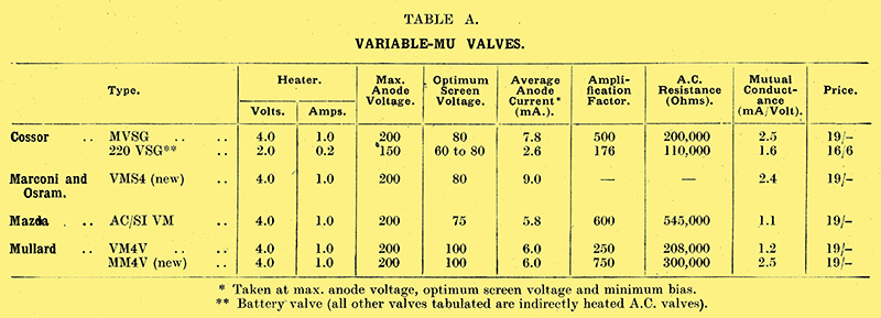
Here is a brief summary of the advantages of the variable-mu valve, together with tabulated data of the working characteristics of all the new valves of this class available. A number of constant screen voltage feeds so essential for the efficient working of these valves are also given.
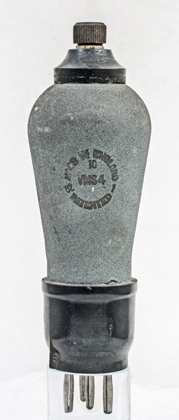
The M-OV VMS4.
Although the mains variable-μ valve first became available so recently as the autumn of last year, it is now to be found in nearly all AC receivers which amplify at high frequency. It would appear to be superseding the ordinary indirectly heated screen-grid valve for the very good reason that there is no function, save one, that the latter can perform which the variable-μ valve cannot perform better. The exception referred to is, of course, anode-bend rectification, which requires a sharp bend in the characteristic the one thing which the designers of variable-μ valves try to avoid.
Neglecting this single function, which is not unduly important, there is a long list of advantages, a number of which have been enumerated before in The Wireless World [1] Sept. 9th, Nov. 4th, Nov. 11th, Nov. 25th, 1931.. It may be as well to remind ourselves of these and others which have come to light more recently: before tackling the problem of voltage distribution between anode, screen, and cathode for the six variable-μ valves now on the market.
Perhaps the most important advantage is that a pre-detector control of volume can be effected over the full range from silence to maximum signal strength by the simple expedient of changing the self-bias resistance. This method does not upset ganging, does not introduce rectification with consequent cross modulation, modulated hum and artificial rise in modulation (HF distortion), and does not entail the shortening of the aerial where the local transmission is difficult to tame. This in itself is enough to justify the employment of a variable-μ valve in place of the screen-grid counterpart, but there are other marked advantages.
When any electrode voltage of an ordinary SG valve is varied considerably from the optimum value in order to reduce stage gain, undesirable effects such as those just referred to take place, and the experimenter must perforce put his faith in a control of volume which cuts down the signal before it gets to the first valve. Not only does this scheme affect ganging, but it means that a weakened signal will receive the full amplification of the valve, so that any valve noise will be fully retained and may account for an irritating background hiss. With the variable-μ valve a signal of 10 Volts - the largest that is likely to be encountered in ordinary circumstances - can be accommodated on the extended or 'tailing' characteristic and, by increasing the bias, the stage gain can be so decreased that even a signal of this voltage can be reduced to a whisper.
The detector stage is seldom designed to accept more than about a Volt, and, with really powerful signals, some form of attenuator is required after the aerial input circuit. Fortunately, at extreme bias the variable-μ valve does actually reduce signals, and hands them on free from valve noise at an amplitude suitable for detection. Another advantage is that the overall selectivity of a receiver with variable-μ HF valves need not, as hitherto, be determined by the pre-selector or aerial input circuit. Due to cross-modulation, in which rectified impulses from the unwanted station modulate the wanted carrier, a multiplicity of tuned inter-valve circuits gives little gain with the ordinary screen-grid valve unless the aerial circuit cuts down the response to very fine limits so that a negligible voltage is developed from unwanted stations.
With the new valves the effective selectivity will depend very much more upon the number of tuned circuits, and, provided that there are sufficient of these in the succeeding stages, there is no need to have more than one before the first valve as cross modulation is negligible. This implies that an input band-pass filter in an HF set is not now essential. In straight sets the degree of selectivity is often not high enough to prevent normal modulation interference from unwanted stations from masking cross-modulation effects, but in superheterodynes the inherent selectivity is so high that until the advent of the variable-μ valve it was almost impossible to design a satisfactory signal frequency HF stage.
It has always been a problem to devise a remote control of volume which is distortion-less and in which no chance of instability arises due to long leads. The variable-μ valves provides a complete solution, as the connections to the variable bias control can be extended to almost any distance provided that serious DC resistance is not introduced. If the receiver-with which remote control is required is a Det.-LF type and the number of tuned circuits cannot be conveniently increased, it is well worth while to use an aperiodic HF variable-μ stage giving an ideal remote volume control besides a fortuitous stage gain of about 5 on the medium Waveband. Should automatic volume control find favour in this country, the variable-μ valve will provide an enormously increased range. In the intermediate-frequency amplifier of a superheterodyne, the variable-μ valve is almost indispensable, as it will not be overloaded with large signals. If this type of valve be used also in the signal-frequency HF stage, it makes possible a simultaneous pre- and post- first detector volume control, an ideal arrangement.
Practical Data
What price must be paid for this impressive array of advantages? True, there is a slightly greater HT consumption when compared with the ordinary SG valve, but what does this matter in a mains set? It is, however, of paramount importance that a feed scheme consisting of a resistance network be provided, so that with change of bias from perhaps 2 to 40 Volts negative the screen volts remain constant, otherwise the harmful rectification effects, which the valve is specially designed to overcome, take place. As the bias changes, so also do both the anode and screen currents, and this alters the voltage distribution in the various resistances. These conflicting factors render the calculation of the necessary feed arrangement somewhat complicated, but fortunately the valve manufacturers have carried out considerable research, and constant screen voltage circuits are shown in Figs. 1, 2, 3, and 4 for all the mains variable-μ valves available to-day. In some cases one or two resistances must be duplicated when two valves are used, as explained in the inscriptions under the illustrations.
No great departure from the resistance values shown should be made, as otherwise the screen voltage will be erratic and will not remain at the optimum figure given in Table A, where the principal characteristics of six variable-μ valves are given. An interesting arrangement is shown for the Marconi and Osram VMS4 valve (Fig. 2), in which it is assumed that the eliminator voltage is 400. When the bias volume control is at its minimum position, the screen and anode currents will be nearly zero, and the valve would in the ordinary way suffer from the application of over 300 Volts. This is avoided by the inclusion of R3 and R2 the latter being ganged to the bias potentiometer so that the increase of current in R2 equals the decrease in current taken by the valve. In this way a constant load is maintained.
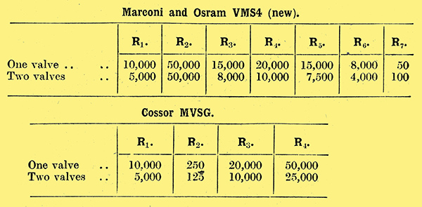
 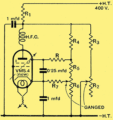
Fig. 1 left. - Cossor MVSG. Data for constant voltage screen feed for one and two valves. The resistances R are for decoupling; that in the anode should have a value of 5 kΩ for one valve and 3 kΩ for two valves, and the screen resistance, which should be duplicated for two valves, can be 600 to 1,000 Ω. Fig 2 right. - Marconi and Osram VMS4 (new). The feed shown here assumes that 400 Volts HT are required for the output stage and that this voltage is applied to the HF amplifier. A variable resistance R2 ganged to the bias potentiometer R6 ensures that the total load remains constant. The resistances R and R7 should be duplicated with two valves.
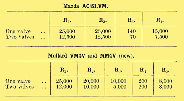
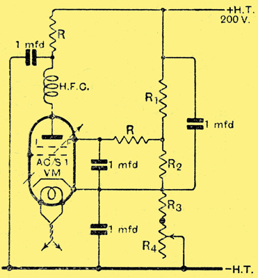 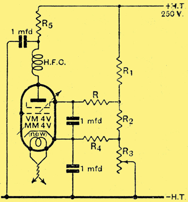
Fig. 3 left. - Mazda AC/S1VM. The resistances R which decouple the anode and screen should have a value of about 600 Ω and both be duplicated when two valves are used. Fig. 4 right. - Mullard VM4V & MM4V (new). The resistances R, R4, and R5 should be duplicated in the case of two valves. The VM4V is not available at the moment but will be released shortly.
|