|

Among the various systems of sound recording for motion pictures in use in this country, that of recording on film by the variable-area method is the most popular. Out of the nine or so concerns which have adopted this method, at least eight use the apparatus devised and developed by RCA Photophone.
Broadly speaking, the equipment can be divided into three parts, microphone, amplifier, and recording camera. The general principle of operation is as follows:- The sound waves are allowed to impinge on the diaphragm of a condenser microphone, and thus set up electrical vibrations with a waveform closely approximating to that of the sound waves. These vibrations are magnified by a voltage amplifier, and then converted into power of a useful magnitude by means of a power stage. From this they are split up into two directions in one to an amplifier which operates a dynamic cone for monitoring purposes, and in the other to the recorder. The recorder is a device for running positive film at a constant speed of 90 ft per minute, on which are photographically registered the electrical vibrations converted into corresponding pulsations of light.
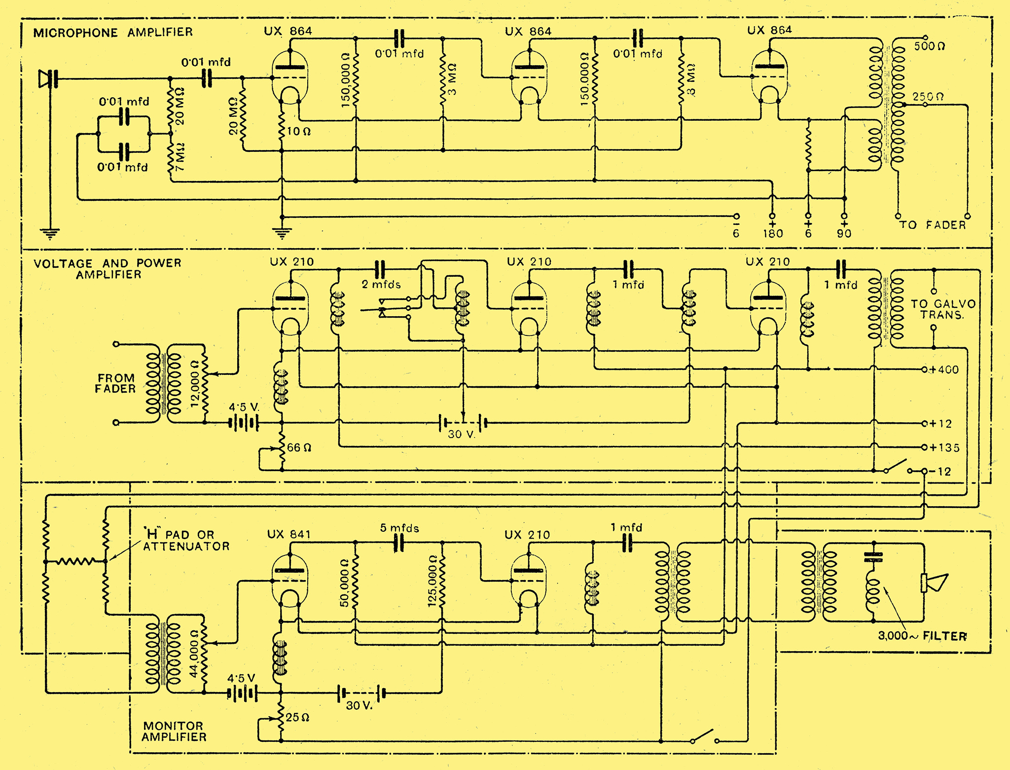
Fig. 1. - Capacity microphone and its associated three-stage resistance-coupled amplifier.
Dealing with the apparatus in a more detailed manner, the microphone proper (Fig. 1.) is seen to consist of a tightly stretched duralumin diaphragm 1.5/1,000 in thick, which is electrically insulated from a back plate and spaced a distance of 1.5/1,000 in from it. A capacitor is thus formed by these two plates, on which is impressed a potential of 180 Volts through a 27 MΩ resistance. The change in capacity caused by the sound waves varying the distance between the plates results in an alternating current being set up in the circuit, corresponding to the sound vibrations. This alternating current produces a varying potential across the ends of the high resistance, which is coupled to the first valve of the microphone amplifier (the circuit diagram of which appears in Fig. 2). In practice the microphone and its amplifier are used as a single unit, battery feeds, etc., being transmitted through a multiple cable. A point of interest is that the output transformer, which is necessarily small, is saved from the risk of saturation by an auxiliary winding wound in opposite sense to the primary, and carrying a portion of the filament current, thus tending to neutralise the field.
The Amplifiers
Fig. 2. - Circuit arrangement of the three units comprising the microphone, power and monitoring amplifiers.
The output of the microphone amplifier is taken to a mixing panel, which can accommodate up to six microphones. This panel feeds a three-stage voltage and power amplifier, the circuit of which is reproduced in Fig. 2. The method of coupling will be seen to be conventional, the valves being coupled by tapped iron-cored inductances, connected as autotransformers, in conjunction with a filter circuit. For the purpose of giving alternative gain, a switch alters the method of connection to the first coupling choke, thus varying the effective step-up of the autotransformer. A choke is connected in the filament circuit to smooth out any interference picked up by long battery leads.
The resistance network connected between the output of the three-stage amplifier and the input of the monitor amplifier is a standard 'H' connection repeater network, or 'TU pad' as it is known in the States, designed to prevent feed-back and howling. Incidentally, the TU or transmission unit, while unfamiliar to many people in this country, is common enough in America. It is a term used by telephone engineers, and is a ratio or measure of amplification. The gain of an amplifier expressed in TUs is twenty times the common logarithm of the voltage amplification.
The Recorder and Optical System
The recorder consists of a sensitive light galvanometer, an optical system, and a light-tight chamber containing the necessary mechanism for drawing the film at a constant speed past the optical system.
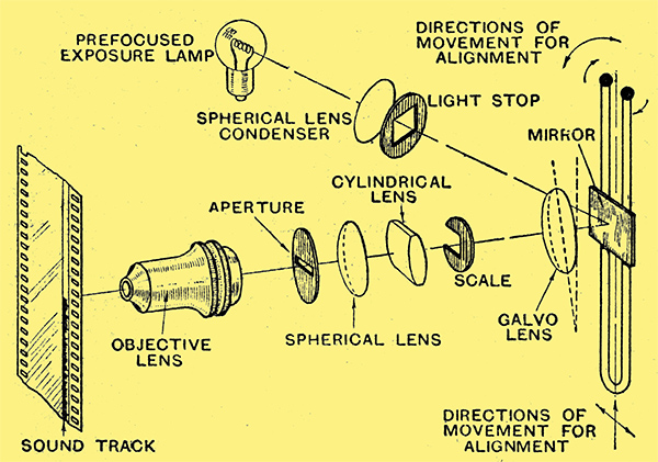
Fig. 3. - Schematic diagram of optical system used tor marginal recording.
The galvanometer and optical system are shown diagrammatically in Fig. 3. The galvanometer consists essentially of a powerful magnet, in the field of which is placed a vibrator. This is a flat wire, 0.5/1,000 in thick, and 5/1,000 in wide, stretched in the form of a loop over two ivory bridges spaced 7/16 in apart, somewhat in the manner of a violin string. The closed end of the loop is taken round an ivory pulley, the position of which is made adjustable, so as to provide for variation in the tension of the wire. The open end of the loop is connected to two terminals. Half-way between the bridges a very small mirror is cemented on to the two limbs of the loop, which are 10/1,000 in apart. This mirror measures approximately 5/64 x 1/64 in. The appearance of the bridges, loop and mirror can be gathered from Fig. 4.
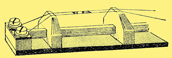
Fig. 4.-The reflecting mirror is carried on a pair of conductors and supported in the field of a powerful magnet.
It will be seen that when the vibrator is placed between the poles of the magnet, so that the looped wire lies across the plane of the flux, the result is in effect a simple motor, except that the armature, or loop, is fixed at the ends and cannot rotate. If, however, an alternating current is passed through the loop, the part between the bridges will vibrate, the mirror vibrating also.
The natural period of the vibrator with the tension correctly adjusted (6 oz) is 6 kHz. The resulting peak in the frequency response is small, and is made negligible by the immersion of the vibrator in a cell filled with a mineral oil. The frequency characteristic of the vibrator alone is given by curve A in Fig. 5.
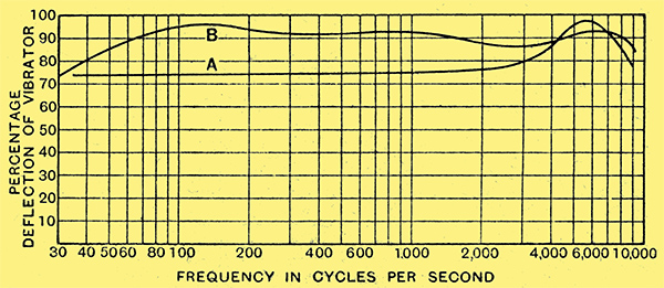
Fig. 5. - Curve A shows the frequency characteristic of the vibrator alone while curve B shows the overall characteristic when the vibrator is combined with microphone and amplifier.
Referring to Fig. 3, it will be seen that light from a special exposure lamp (consuming 4 Amps at 5 Volts) passes through a double convex condensing lens and through a light stop on to the mirror. The lens seen in front of the mirror is a plane lens acting as a window, preventing the damping oil from escaping, and is mounted at an angle, so that light will not be reflected from its surfaces into the remainder of the system. The light is then reflected from the mirror through a cylindrical lens, which condenses the beam in one direction. It is then condensed still further before it passes through a slit in a disc. This slit is 3 /1,000 in wide, and allows the light to pass through it into a microscope objective lens, with a 4:1 reduction. The objective focuses the image of the slit on to the film, resulting in a light image of 0.00075 × 0.070 in In practice half the light beam is intercepted by a celluloid screen on which are inscribed two lines. One line denotes the limit of the beam under conditions of no modulation, in which case half the sound track is exposed (under modulation the beam moves laterally); the second line on the scale denoting the position where the light has reached the full width of the track, and past which it cannot move without overshooting and producing consequent distortion. When the track is overshot the tips of the peaks are not registered. When the output of the power stage in the amplifier is applied through a step-down transformer to the two ends of the vibrator loop, the mirror vibrates in sympathy with the impulses. This varies the length of the slit image on the film, and produces a sound track of varying width.
The film is moved past the optical system at a constant speed of 90 ft per minute in synchronism with the film in the mute camera. In order to attain complete synchronism, the motive power for both cameras is obtained from synchronous motors, driven from a common three-phase source. In the sound camera a special gearing drives a supply sprocket, the recording drum, through a special compensating mechanism, and the magazine take-up. The purpose of the compensator is to allow for the shrinkage or expansion existing in different stocks or grades of films. The film is drawn from the magazine by a sprocket at constant speed, from whence it passes over the recording drum into the take-up box. If the film were stretched, a loop would tend to form between the sprocket and the drum. It is essential that the linear speed of the film past the recording drum be constant. The sprocket speed is constant, but in the case of a stretch the linear speed would become slower. Accordingly, use is made of the above-mentioned loop to increase the speed of the drum. This will be understood more readily on reference to Fig. 6.
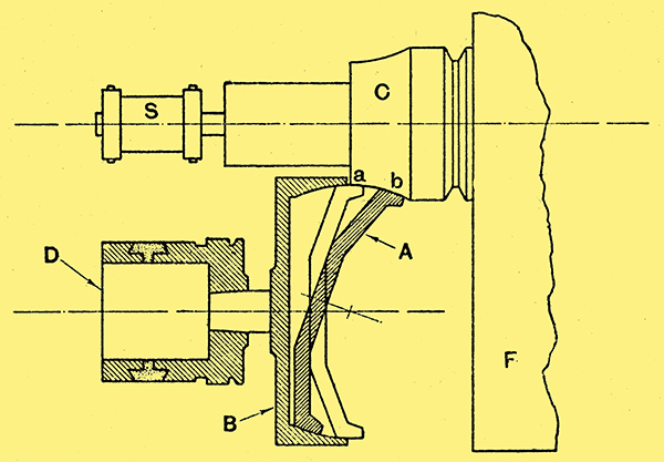
Fig. 6.- Compensator mechanism for allowing for variation in the stretch of the film.
Driving Mechanism and Film Carrier
The flywheel F is driven by a synchronous motor through a pinion and gear. On the same shaft as the flywheel is a cone C and sprocket S, which pulls the film from the magazine at constant speed. The shaft floats on a supporting arm. A spring, exerting pressure on this arm, forces the cone C on to an idler A, causing the idler to revolve by friction. Pressure from the cone C is transmitted through the idler to the cylinder B, driving it also by friction, and thus causing the drum D to revolve. It is evident that the speed of the drum is dependent on the position of the idler. If the idler is in position a the drum will revolve slower than if it were in position b. The position of the idler is changed by a tilting lever which is controlled by a compensating roller. Thus, if the film has been stretched at any part, a loop tends to form between the sprocket and the recording drum. This allows the roller to drop, causing the compensator to move the idler into a position to increase the speed of the recording drum, and take up the slack film. With shrinkage in the film the reverse takes place. The position of the compensator is indicated by a pointer on the door of the recorder. The complete machine is carried on a table on which are mounted switches controlling the power supply, signal lamps, etc. Fig. 7 shows the recorder, the control switches and the meters on the table.
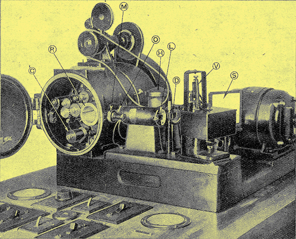
Fig. 7.- RCA photophone recorder showing the complete mechanism and control switches. C is a compensator roller; R, recording drum; M, marker lamp; O, objective lens; H, lamp housing; L, cylindrical lens; D, deflecting prism; S, light screen and V, vibrator.
In practice, the amplifier rack, an illustration of which is reproduced (see Fig. 8), is mounted together with the monitoring loud speaker and communication phones in a portable booth on the studio floor. From here the recordist can follow the action on the set. The recorder table is either housed in a compartment adjacent to the amplifier, or in a room near to the studio floor. In the first case, the recordist watches the light on the celluloid scale through a window. Sometimes the portion of the light normally intercepted by the scale is passed through a prism and projected on to a ground glass screen as an image an inch or so in width, thus being easier to see from the recordistbs chair.
In the second case, use is made of either a modulation meter or of a second optical system installed in the booth, and calibrated with that on the recorder. A volume indicator, or modulation meter, is fitted as standard on the panel. This is really a valve voltmeter with a meter showing the rectified output. The method of using a second optical system is by far the best, as a meter needle with its inertia will not respond to transients and high-frequency peaks. The primary windings of the two step-down transformers, which are associated with the galvanometer, are series connected.
In order to ensure accurate synchronising during printing, when the soundtrack and picture are combined, a system of marker lamps is used. The edge of each film is exposed for a few seconds at intervals by lamps, connected in series. These are controlled from the recorder table.
The light from the exposure lamp may be checked at intervals by means of a calibrated photometer, which can be plugged into the recording drum. The sound track is always exposed and developed to a density of 1.4. It is not considered safe to adopt a higher figure than this, owing to the danger of fog or halation filling up the valleys in between the high-frequency stations. The valves used in the three-stage amplifier and in the first position of the monitor have constants similar to those of the Marconi or Osram LS5 and LS5B valves respectively.
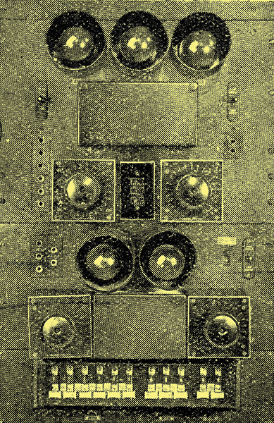
Fig. 8. - Recorder three-stage amplifier, monitoring amplifier and fuse panel.
|