|
Low frequency power compensation. It is here pointed out for the first time that a very considerable improvement in bass response can be effected by the use of quite a small capacity in the choke filter output circuit of a pentode. A capacitor of about one-eighth of the usual capacity is made to resonate with the output choke at low frequencies and a circuit very similar to that of the parallel-fed LF transformer results. The resonance is damped out by the low impedance of a triode but remains almost unaltered by the high pentode impedance. Many practical examples of the arrangement are outlined.
The pentode output stage differs from that of the power triode by several interesting peculiarities which arise from the high and variable resistance of the pentode. For example, there is the practice of matching the pentode to a load of much smaller impedance than its own nominal impedance, and of placing a resistance and small capacitor across the load in order to maintain roughly the same overall load impedance at all frequencies. Thus, if The Wireless World Valve Data Sheet he consulted, it will he found that optimum load values are quoted for all pentodes, and, though it is not the practice to show the pentode resistances because of their variability, it may be taken that the optimum load values are in all cases below the average nominal resistances of the pentodes to which they apply. Again, the makers instruction leaflets usually contain suggestions for suitable resistance-capacitor combinations to employ across the load, together with special warnings as to the undesirability of tampering with the output circuit whilst the pentode is in operation on account of the high peak voltages which may be produced.
Readers who wish to recall in detail the reasons for the above will find them dealt with in various past articles in these pages, but the author would refer them particularly to an article early in 1929 [1] The Pentode and Power Amplification, L G A Sims, The Wireless World, Vol. 24, No. 490, January, 1929., in which some of the practical aspects of pentode loading were dealt with for the first time. The subject of the present article developed as a result of earlier experiments upon the pentode which are described in that article.
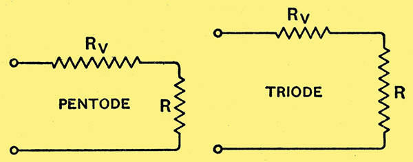
Figs. 1 and 2.- The relative resistances of valve and load are shown in these two illustrations for the case of the pentode and triode.
It is sufficient now to recall that there is an important fundamental difference between the output circuit conditions for the pentode and the triode, which can be indicated diagrammatically, as in Figs. 1 and 2, where a skeleton output circuit, consisting of the internal resistance of the valve in series with a resistance to represent the load, is shown for the pentode and triode respectively, the relative values of the resistance in each case being indicated very approximately by their lengths in the diagram. The valve resistance is marked Rv and that of the load R, and it is seen that, whilst the pentode works with a comparatively low load resistance, the case of the triode is just the opposite, as its load is comparatively great.
Capacitor Values
Now, in practice, Rv and R may be coupled together in any one of three different ways: (1) directly, as shown; or (2) by means of an output transformer; or (3) by means of a choke-capacitor unit. A little mathematical analysis shows that the last case, namely, that of the choke-capacitor output, is affected in a very marked manner by the relative values of Rv and R when a pentode is used as the output valve.
Stated briefly, the output from the pentode at low frequencies can be increased very greatly by the presence of the coupling capacitor, whereas the triode output is not affected in the same way.
It is at present common practice to use an output coupling capacitor of 2 μF indiscriminately with both types of valve. This value is specified presumably because it has always been satisfactory with the triode. But the fact is that both mathematics and experiment show that a smaller value of capacitor leads to a greater output at low frequencies from the pentode, though, in accordance with popular belief, it reduces the output of the triode.
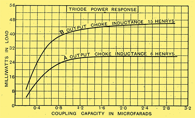
Fig. 3. - With a triode the power output is changed very little when the choke filter condenser is increased from one to three microfarads. The valve used was a P240 type and the frequency 50 Hz.
Figs. 3 and 4 will make this clearer. Fig. 3 shows two experimental curves taken with a typical modern triode output valve at a frequency of 50 Hz. It is seen that the power delivered by the valve increases steadily as the capacity is increased and that a 2 μF capacitor is entirely satisfactory, though, if anything, unnecessarily large. But a reduction to 1 μF, though practicable, would be suggested only from the viewpoint of economy in the cost of the capacitor, not from any advantage in power output.
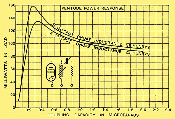
Fig. 4.- Quite an appreciable drop in power output results from an increase of capacity from 0.3 to 2 μF in the choke-filter capacitor in the case of a pentode (valve used PT240 and frequency 50 Hz).
But Fig. 4 shows a quite different result. The curves i.n this figure relate to a typical pentode. It is clear that a 2 μF coupling capacitor gives much less power output than one of about 0.3 μF.
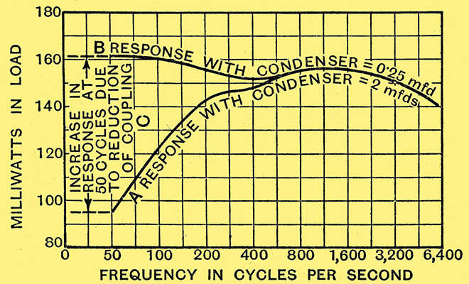
Fig. 5. - Curves showing the marked improvement in bass response when using an 0.25 μF coupling capacitor as compared with a 2 .0 μF capacitor in a pentode output circuit.
This result is demonstrated again in a very practical manner by the curves of Fig. 5. Here the power response curve of the same pentode is plotted from experimental results taken over a range of frequencies between 50 Hz and 6 kHz. The lower curve refers to the power output using a standard commercial choke-capacitor unit containing a 2 μF capacitor. The upper curve shows the result of reducing the coupling capacitor to the value of 0.25 μF.
So far as the author is aware, this peculiarity of the pentode power stage has not previously been pointed out. It is a direct result of the special load conditions which, as is now well known, have to be employed with the pentode in order to avoid anode-voltage peaks and distortion of output.
Careful measurements show that the use of what we may now call Critical Capacity coupling may compensate, the low-frequency power response to almost any desired degree. For example, provided that the coupling; choke has a fairly high inductance, the normal droop in the low-frequency response (see Fig. - 5, lower curve) may be either raised to the extent that the curve becomes almost perfectly straight from, say, 50 Hz up to the high audio frequencies, or, if desired, may be converted into a hump, thereby tending to compensate for deficiency in the bass response of the loud speaker.
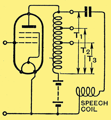
Fig. 6. - Conventional pentode circuit with tapped output choke.
Since the critical value to be employed in any given case may differ somewhat according to the other components in use in the circuit, it is necessary to examine such differences, and, in the present instance, this is best accomplished by further experimental curves. For example, if Fig. 6 represents the essential components of a pentode output stage, the equivalent circuit for which is given by Fig. 7.
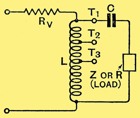
Fig. 7. - The equivalent electrical network of Fig. 6.
We have to know how the critical value of capacity is affected by changes in the load impedance, by the choke tapping point T1, T2, or T3, to which the capacitor and load are connected, by the inductance of the choke and by different pentode internal resistances.
Effect of Load Impedance
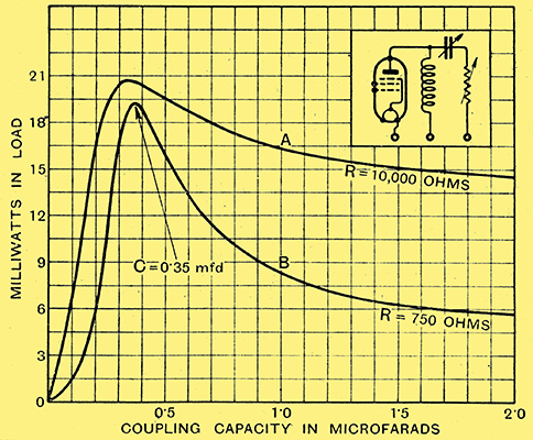
Fig. 8. - Curves A and B show how change of load affects the output when the capacitor capacity is altered. The output at 'critical capacity' in both cases is the highest.
Fig. 8 shows curves of 50 Hz power plotted against change of coupling capacity for two widely different values of load, other conditions being kept constant. Curve A relates to a load consisting of a resistance of 10 kΩ and curve B to one of 750 Ω. The curves show that the critical capacity is not affected by this very large variation in load conditions, though the percentage increase of power at the critical value of capacity is very much greater for the low resistance. Now, the loud speaker is, of course, the most usual form of load, and this has a variable impedance which is lowest at the low frequencies, so that the critical capacity would seem to be particularly effective if used in a practical output stage.
The curves so far dealt with have all shown a capacity of about 0.25 to 0.4 μF for 50 Hz, and it is well to review the cases taken in order to see what has been covered. Fig. 4 showed that changing the choke inductance from about 25 Henrys to about 40 Henrys changed the critical -capacity from about 0.35 μF to about 0.25 μF, whilst Fig. 8 showed that changes in the load resistance did not affect the value of capacity at all. But all these curves related to a tap ratio of unity, that is, to the tapping position T1 in Fig. 7. What modification will be introduced by connecting to positions such as T2 and T3.
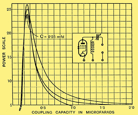
Fig. 9. - The effect of changing the choke tapping (or auto-transformer ratio) is shown by the curves. Frequency 50 Hz.
Fig. 9 provides the answer to this question, for it shows curves plotted for different taps on the coupling choke. If these curves be examined it will be found that the critical capacity value varies according to the square of the tapping ratio. Thus, for example, with a centre-tapped choke the capacity will be four times as great as with a plain untapped choke because the tap ratio of the former is two, and so on. This simple relationship is very convenient.
Tapping ratios greater than about 3 to 1 are mainly used with low-resistance moving-coil loud speakers, and the curves of Fig. 9 teach that, in this case, a well-designed output transformer is to be preferred to a choke-capacitor unit as the value of capacitor required in the latter increases alarmingly as the tap ratio goes up - see, for example, the curve for the modest ratio of 3 to 1, where 3.6 μF is necessary for maximum power, and the usual 2 μF is then much too small.
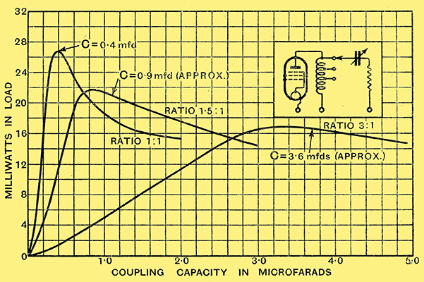
Fig. 10. - With an untapped choke and three modern pentode output valves the above curves speak eloquently of the effect on power output of the critical capacity.
We have now only to examine curves showing the effect of changing the pentode and of using an actual loud speaker in place of a resistance as a load. Both these cases are included in Fig. 10, where curves for three different pentodes working into a modern inductor-dynamic loud speaker are shown, an untapped choke being used. It will be seen that changing the pentode has practically no effect upon the critical capacity value, which in this case was about 0.25 μF, whilst the presence of an actual loud speaker accentuates rather than diminishes the effect we are dealing with. The possibility of this was foretold earlier in the article. (It should be, stated that the voltage input to the different pentodes in this test was not the same in each case. This was necessary because of their different amplifying properties in order to avoid too great divergences between the curves. It does not affect the capacity values).
This completes the examination of all the variable quantities in the circuit so far as space permits in the present article, and, to summarise results, it may be said that the value of the critical capacity for a given frequency is practically independent of all the circuit components except the choke. The inductance of the latter, if of the normal value of about 30 to 40 Henrys, causes small changes above and below 0.3 μF for the frequency of 50 Hz. The ratio of the choke tap may cause large changes which, however, are proportional to the square of the ratio.
Capacitor-fed Transformer
It should be clear that, although the treatment of the case has been based upon a frequency of 50 Hz, this is in no sense a fundamental frequency. The same arguments apply throughout the low-frequency band, and therefore, if any small capacity of the order 0.3 μF is used as an output coupling, it will tend to compensate the low-frequency response, being, however, particularly effective at one frequency, Thus an capacitor of capacity 0.1 μF will compensate most strongly in the region of 100 Hz. On the other hand, larger capacities will tend to compensate at still lower frequencies than 50 Hz, but the compensation is weaker. So long as a pentode is in use compensation in some degree will occur with a wide range of capacity values [2] Even with the triode a, coupling capacitor may give a slight power increase, but there is no value which will either completely compensate or over-compensate the response curve at any point in the bass register, and strictly it is in this special respect that the pentode differs., but the most valuable effects from the point of view of correction of the deficiencies of the normal response curve are given by capacities of the order 0.3 μF and this value is recommended for trial or the correct multiples of it where the tap ratio is not unity.
Now, although the treatment so far given relates to choke-capacitor coupling particularly, why not apply it to the output transformer also, provided that its ratio is not so great as to call for the use of an unduly large capacitor? The output choke, whether tapped or not, is, after all, a transformer of the special type known in power engineering as an auto-transformer.
A theory which applies to the output choke will therefore apply equally well to tlle output transformer, and a capacitor inserted in series with the load on the secondary side of such a transformer will increase the power delivered, especially if the capacitor has the critical value as defined above. This gives a means of increasing the bass response of a poor output transformer.
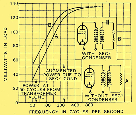
Fig. 11. - The effect on bass response of including appropriate capacity in output transformer circuit.
For example, Fig. 11 shows the output from 50 to 1,600 Hz of a 1.5 to 1 output transformer whose bass response was not too good. The lower curve relates to the transformer as designed, and the upper one is a repetition, with a capacitor of capacity 0.8 μF in series on the secondary side. This was the critical capacity for 50 Hz, and if we divide it by the square of the transformer ratio we obtain a value which is in line with the results obtained upon untapped output chokes. It is seen that the presence of the capacitor increases the power at 50 Hz by about 70%. The increase would have been much greater had the transformer had a larger primary inductance.
This is a point of further interest-output transformers usually have less primary inductance than output chokes because there is less room inside for a large primary winding. But this is all the more reason to experiment upon applying bass compensation by the use of critical-capacity. Fig. 12 shows the power-capacity curve for a pentode and output transformer, with capacity added in the secondary winding, working into a loud speaker. The normal transformer power level is indicated by a dotted line.
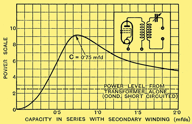
Fig. 12. - Power-capacity curve for pentode transformer output working into a speaker load.
In conclusion, the author would say that his own experiments upon the subject outlined in the article have necessarily been confined more to laboratory measurements than to aural experiments upon receivers reproducing broadcast, but such trials as he has been able to make of critical capacity coupling in conjunction with speech and music seem entirely favourable to its use. Moreover, there seems no theoretical reason why this should not be so. Loud speakers differ greatly, but even in those cases where the low-frequency response is not strikingly improved by the much smaller capacitor, due to the characteristic of the speaker and of the human ear, at least an economy in capacitor cost may be found possible. The 'phase' relations in the region of the critical condition undergo rather violent changes, and it would be very helpful to have the opinion of amateurs who care to apply the principle in their receivers and note carefully the results. A few capacitors of capacities 0.05 and 0.1 μF which can be connected in parallel step by step would make an ideal test equipment. For the rest, a pentode and a good-quality choke and loud speaker (capable of reproducing the low bass register) are all that is necessary. The usual high-note filter across the speaker will not affect the experiment adversely, but it is desirable to switch off the pentode during alteration of the circuit.
|