|
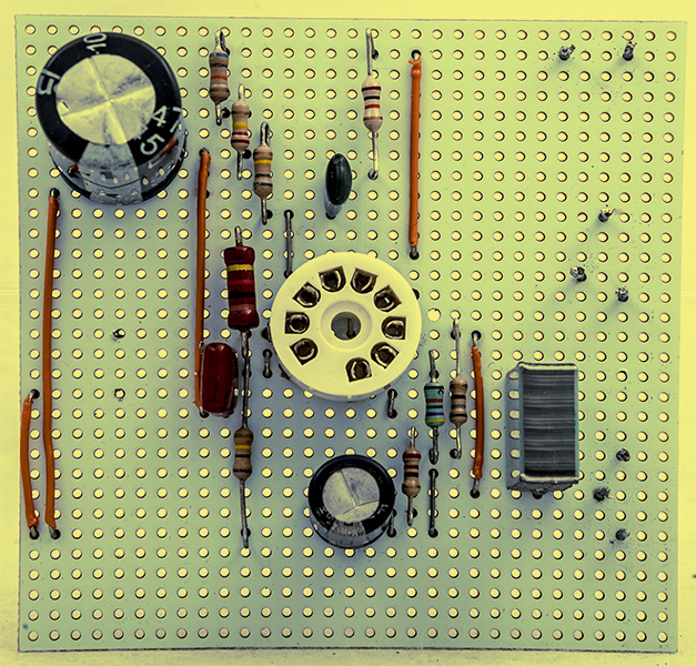
The amplifier built on strip-board.
The author started the build a year ago and only got as far as mounting the valve-holder. The board then sat on the bench waiting for attention.
The strip-board layout was drawn in several iterations, each time the changes were made to minimise the interaction of input and output and keep the capacitors away from the heat of the valve. All of the ground connections were made to a single strip. An input capacitor of 2.2 μF was added and a fixed resistor substituted for the input potentiometer.
It was a joy to fire-up the soldering iron after many months of other tasks and the build slowly took shape. An output transformer of 11 kΩ primary impedance was not available but a 3 Watt 10 kΩ single end EL95 transformer was to hand and this was used. Two NOS ECL80's were available one Mullard and the other from Mazda. The heater was run from DC and the HT supplied from the Heathkit IP-17 stabilised bench power supply. The signal generator was the GW Instek AFg-2112. The latter was connected in place of the original crystal pick-up used in the original. The HT unit was not earthed as the signal generator provided the earth connection.
After the heater had reached working temperature the HT was applied starting with a very low voltage. The 1 kHz tone was immediately heard. As the voltage was slowly increased the amplifier broke into powerful low frequency oscillations - motorboating. The test was aborted and the circuit checked again for connections, joints etc. Nothing incorrect was found.
Motorboating was common in earlier times and usually the problem was supply decoupling or a faulty capacitor. Extra decoupling was added but the instability remained. Running the amplifier from a stabilised low voltage power supply at 26 Volts kept the instability to a minimum.
A rough examination of the frequency response at 26 Volts HT voltage indicated that the gain was way down above 8 kHz as the treble filter in the circuit started to operate. Clearly 1950s record players had no need of Hi-Fi.
The cathode bypass capacitor was removed - the instability just changed frequency. The bypass capacitor was increased to 2,200 μF - still unstable but with a lower note. The original 100 μF bypass capacitor was reinstated.
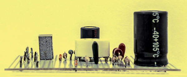
Next the screen grid feed was changed from a direct connection to the HT line to having a 1 kΩ resistance in series with the grid. The grid was decoupled to chassis with a 47 μF capacitor. Not even a slight improvement.
The Mullard ECL80 was swapped for the Mazda - no change. The PCL83 has separate cathodes but essentially the same pin connections as pin 3 and 7 were connected together on the ECL80. With the heater changed to 12.6 Volts the HT was re-applied - still the same instability.
It looks like the method of construction coupled with the tendency for these valves with common cathodes to become unstable is the fundamental problem.
The author is unlikely to rebuild this circuit on an open chassis with VHF style single point earthing. However, with the EL95 output transformer to hand and a PCL83 a small amplifier could well emerge soon.
The amplifier built on strip-board.
|