|
Few people in 2022 would build a valve based oscilloscope. However, there are many projects such as CRT clocks that require a basic CRT power supply for small diameter tubes. This practical design with a conventional mains transformer will be the basis of a CRT tube network operating with modern DC/DC converters for EHT, HT and heater supplies. -Ed.
In past issues of this magazine there have been published a number of articles describing the construction and use of the cathode ray oscilloscope, and it must be admitted that the subject has had its full share of space in this and other periodicals.
In submitting the present instrument, however, it was thought that the comparative simplicity, together with the compact design, would appeal to those readers who had contemplated the building of an oscilloscope but who had not done so, on the grounds that most designs had either only the bare essentials or else were too complex.
This instrument is for general purpose use, and in the writer's opinion serves that purpose to good effect.
Waveform analysis, frequency comparison, receiver alignment and an indicator with high impedance input are some of the uses to which the instrument may be put.
The diagram of the chassis and layout are self-explanatory and, as it is assumed that most constructors have a working knowledge of metalwork, no detailed description of this part of the job is given.
The main frame consists of ¼ in square steel bar bent to the required shape and supported at the ends by the front and rear panels. The front panel holds all the main controls and terminals, while the rear panel is plain with the exception of a ⅜ in rubber grommet through which the mains lead passes.
All components, apart from those on the front panel, are situated on both sides of a platform which passes down the centre of the main frame. The platform also holds the main double-sided tag panel and rear support for the CRT. The outer casing consists of aluminium panels, with ventilation louvres in the top section and circular holes in the bottom section to permit the entry of cool air.
The side panels are screwed to the main frame, and the top and bottom panels are fixed to the side panels. This fabrication of the case was considered easier to construct than a one-piece box.
Designation of the front panel terminals and controls can be made with Panel Sign Wording No. 3.
HT, EHT and Tube Network
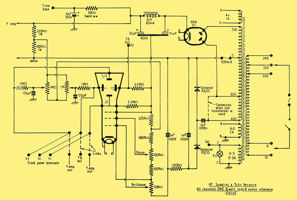
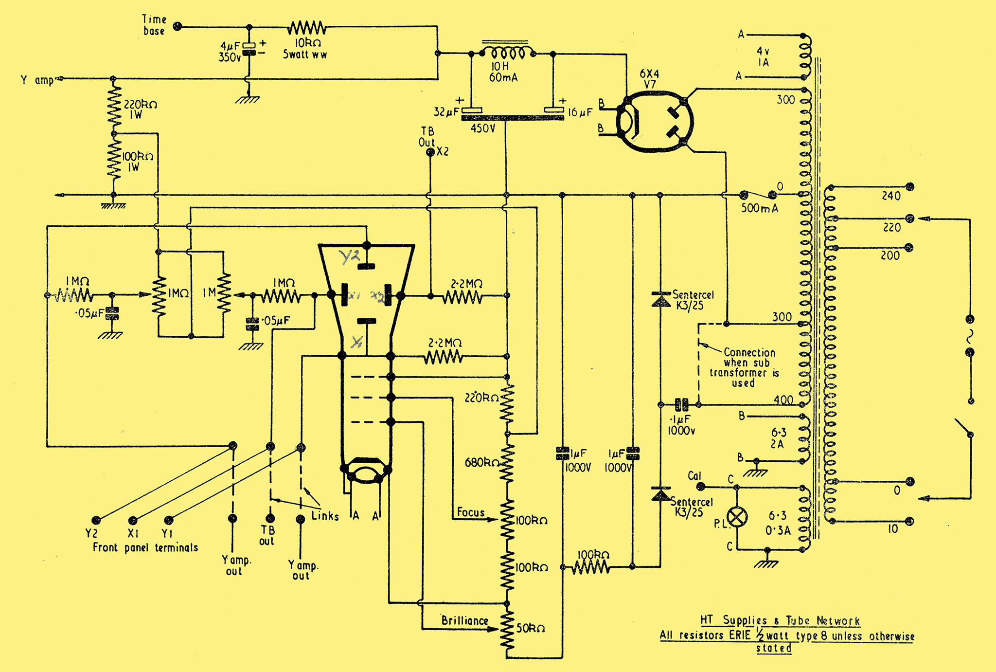
The 1957 circuit diagram.
The HT and EHT supplies are all provided by a standard transformer modified to suit the requirements of the instrument. The writer was fortunate to have in the spares box a transformer of the older type which possessed a bobbin with side cheeks and a 350-0-350 V HT secondary. The next job was to strip the heaters and HT secondary from the bobbin, care being taken to ascertain the number of turns-per-volt of the heater windings, as a basis for the calculations needed for the modified HT and heater windings.
The primary winding was checked and found to be satisfactory, so a start was made on the HT secondary. This was wound with SSE wire two gauges smaller than the original, as the loading was lower, and the single silk covering disposed of the need for interleaving. As the total over-all voltage of the winding (300-0-300-400) was the same as the old one, it occupied approximately the same space, and left plenty of room for the three new heater windings required. Reference to the power pack schematic will give details of the loadings to provide for.
- Winding A, Tube Heater, 4.0 Volts, 1 Amp, 22 SWG SSE.
- Winding B, Valve and Rectifier Heaters, 6.3 Volts, 2 Amps, 20 SWG SSE.
- Winding C, Pilot Lamp and Calibration, 6.3 Volts, 0.3 Amps, 28 SWG SSE
The rectifier used is a miniature 6X4, the cathode-heater insulation of which is high enough to enable it to be used on the winding supplying the other valves.
The pilot lamp winding also serves the purpose of supplying a calibration voltage, which is brought out to a terminal on the front panel.
For those constructors who would prefer to wind a transformer complete and have the facilities to do so, the necessary details and winding data are given.
The first materials required are a 1¼ in Stack of T and U Silcor laminations No. 475A, and a bobbin to suit. When these have been obtained, winding may commence.
- The primary is wound with 1,490 turns of 30 SWG with tappings at 60, 1,250 and 1,370 turns.
- HT Secondary: 4,430 turns of 36 SWG with tappings at 1,900 and 3,800 turns.
- Heater Sec. (1) 40 turns of 20 SWG (6.3 Volts, 2 Amps).
- Heater Sec. (2) 40 turns of 22 SWG (6.3 Volts, 0.3 Amps).
- Heater Sec. (3) 26 turns of 22 SWG (4.0 Volts, 1 Amp).
Wire used is single silk-covered enamelled copper with no layer interleaving insulation. Inter-winding insulation is three layers of 0.010 in Empire cloth.
It is possible that a number of enthusiasts will not have the facilities to modify an existing mains transformer, or wind a new component to the specification given.
There are others who do not feel capable, or who consider that they have not had sufficient experience, to cope with the work involved in modifying or winding their own transformer.
Constructors, therefore, who desire to purchase a ready-made article which will provide a satisfactory substitute for that specified, are advised to contact Messrs. H Ashworth, 676 Gt. Horton Road, Bradford 7, Yorks., who have a suitable component in their advertised list.
This is a half-shrouded job which will fit into the space provided on the chassis, and requires no alteration before being put into use.
The type no. is HS30, and it is to the following specification:
- Normal Primary 200-250 volts.
- Secondary 300-0-300 Volts
- Heater 1, 6.3 Volts tapped at 4 Volts at 4 Amps.
- Heater 2, 5.0 Volts tapped at 4 Volts at 2 Amps.
It will be noticed that in using this transformer the half HT secondary connected in the EHT voltage-doubling circuit is only 300 Volts instead of the 400 Volts provided by the extended winding on the specified design.
This will result in a fall in the final voltage applied to the CRT anode, which will, in turn, slightly alter the operating characteristics of the tube.
It will be found that the spot size, when in optimum focus, will be enlarged, and that the overall maximum brilliance will be diminished.
One point, however, in favour of a decreased EHT supply is the subsequent increase in the deflection sensitivity.
The 6.3 Volt heater winding supplies all the valves, including the rectifier. In the absence of a separate winding the pilot lamp and calibration voltage are also supplied from this source.
The 4 Volt tapping on the 5 Volt heater winding, which normally is used to feed a rectifier heater, is in this case pressed into service as the CRT heater supply.
Finally, it should be borne in mind that this transformer is only a substitute, and some slight deterioration in performance is to be expected if the original design specification is not used.
The 6X4 is employed in a full-wave circuit, and smoothing is effected by a conventional capacitor input filter which needs no comment. The supply is passed to the Y amplifier direct, but the timebase rail contains a further decoupling network to drop the voltage to a suitable level.
EHT current is supplied by the 400 Volt extended winding on the mains transformer in conjunction with a voltage doubling circuit. The rectifiers used are the selenium pencil type and are Sentercel K3/25's. Smoothing is provided by an RC combination suitable for high voltage-low current supplies, the final potential being approximately 800 Volts. This was found to give sufficient brilliance together with adequate deflection sensitivity.
The tube diameter is 2 in, which was considered to be not only the ideal size for a scope but easy to obtained from ex-service sources, and modest in its operating requirements. The 23D is typical of this type of CRT.
It should be mentioned at this point that when a tube is purchased it is essential that the mu-metal screen, which in most cases covers the tube, is bought at the same time.
Due to the compact nature of the construction and the close proximity of iron-cored components to the tube, it will be impossible to avoid the undesirable effects of external magnetic fields unless this screen is fitted.
The normal X and Y shift controls are included, the DC voltages being supplied by a network across the HT and EHT sources.
It should be noted that extra insulation in the form of Paxolin bushes is provided on the front panel for the spindle bushes of the focus and brilliance potentiometers. This precaution was considered necessary in view of these components being at a high negative potential to earth.
Provision is made to enable direct connection to be made to the X and Y plates by removing the links situated on a small panel on the right-hand side of the chassis. When the links are in position, amplifier and timebase outputs are available on the front panel terminals. Access to the links is provided by an opening in the side panel which is normally closed by a small cover plate.
|