|

Remarkable mutual conductance achieved by close spacing.
The recourse to extremely small clearances between the electrodes in a valve to obtain improved characteristics has always been regarded as a theoretical possibility. Hitherto this has only been attainable in laboratory-made specimens, but hardly practicable where valves are made under conditions of quantity production.
Mechanical rigidity and the difficulty of avoiding undue temperature rise of the grid electrode in particular appear to have been the limiting factors, since if its temperature rises above a certain level grid emission ensues.
These difficulties have now been overcome successfully in the new Micromesh valves made by Standard Telephones and Cables, Ltd., and, although the clearances between the various electrodes are extremely small, indeed much smaller than. it has been found possible to adopt by normal methods of construction, effective cooling of the grid has been achieved and a mechanically strong structure evolved. So effective is the cooling that, even though the cathode and anode are raised to a dull-red heat, there is no trace of grid emission.
As a result, exceptionally high amplification properties and very good mutual conductance values are obtained, while the particular method of construction adopted has proved entirely satisfactory in quantity production.
Magnesia Insulation
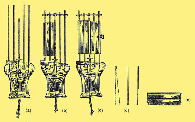
Details of the electrode assembly; (a) the cathode; (b) grid and its cooling fin; (c) the complete assembly; (d) heater, cathode and Magnesia insulator; (e) showing construction of - the grid.
Emerging from the pinch of the valve are seven wires; in the middle is the cathode support, with the two heater connections adjacent, While on one side are the two grid supporting wires, and on the other the two anode supports.
Since the cathode must of necessity be adequately insulated from the heater, but at the same time make good thermal contact, the heater wires are crimped and then threaded through twin bores in a Magnesia insulating tube; this, in turn, is arranged to grip the cathode firmly, but the whole structure is permitted to move in an axial direction to compensate for thermal expansion. A guide wire is inserted, therefore, in the upper end of the assembly and passes through a guide fixed to a mica bridge held in position by extension of the anode and grid-supporting wires.
Normally, the cathode runs at a dull-red heat and takes about fifty seconds to attain the full emission state, which comparatively long period is due to its robust construction, giving good mechanical strength in addition to adequate electrical shielding. The heater requires about 1 Amp at 4 Volts.
The assembly of the grid and anode electrodes and the method employed for mounting them is of paramount importance, for, as mentioned above, it is only by providing for rapid dissipation of heat, especially in the case of the grid, that it has been possible to work to such close clearances as obtained in Micromesh valves. Both anode and grid are fitted with large rectangular fins which serve the dual purpose of supporting their respective element and provide a large area for the radiation of heat.
The grid consists of a series of wires welded at either end to each half of the cooling fin, the welding extending as far as the inside channel in the fins. Thus perfect thermal contact is assured and the structure is very strong mechanicallyb, an essential feature in view of the.very small clearance allowed between adjacent electrodes. When finally completed, the grid takes the form of a flat fin having two longitudinal channels which embrace the supporting wire, while the effective portion consists of a series of wire loops enclosing the cathode.
Exceptional Characteristics
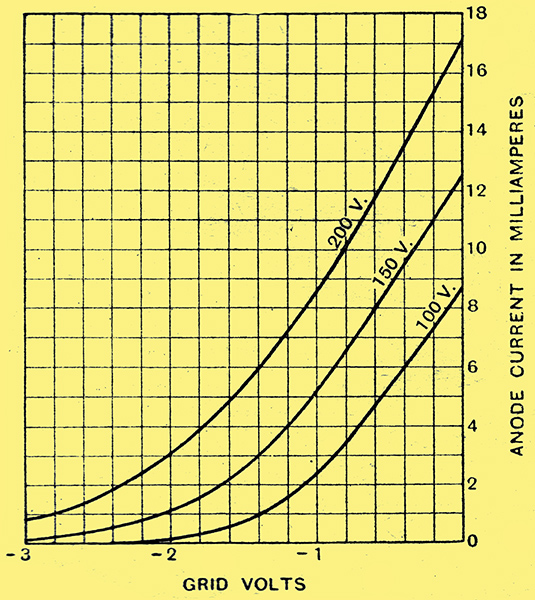
Curves connecting anode current and grid volts for Micromesh HLA1 valve.
The anode is assembled in a somewhat similar manner, but with the exception that the portion enclosing the grid is fashioned in the form of a tube with a longitudinal slot through which passes the grid fin. That this novel method of construction has been fruitful in producing valves of outstanding merit is well exemplified by the exceptional characteristics exhibited by the advanced specimens sent in for test. These consist of a detector, a power amplifier, and a mains rectifier. The detector, which is given the designation HLA1, has the following characteristics when measured with 100 Volts HT and zero grid bias:
AC resistance, 10,000 Ω. Amplification factor, 80. Mutual conductance, 8 mA/V.
Although the maximum anode potential is 200 Volts, as a cumulative grid detector it functions quite satisfactorily with but 100 Volts on the anode. For power grid detection the valve may be operated with any value of HT up to the maximum, the only limiting factor being the current handling capacity of the components in its anode circuit, for, as a matter of interest, the valve will pass up to 25 mA without sustaining damage.
A Slope of 12.6
The HLA1 is admirably suited to the amplification of small input voltages, and can be employed, with advantage, in the first stage of a gramophone amplifier, but it is often more convenient to utilise the detector and output valves of the broadcast receiver for this purpose.
Despite the high amplification of the valve and the very small clearances between the electrodes, by careful design the anode to grid capacity has been kept down to the very low figure of 5 μμF, so that the damping of the grid circuit is by no means as great as the high mutual conductance might seem to imply.
Under normal operating conditions the temperature of the glass bulb becomes somewhat higher than usual for valves of this type, and it will be necessary to provide adequate ventilation of the cabinet. For unless this precaution is observed it may nullify the cooling effect of the grid and anode fins.
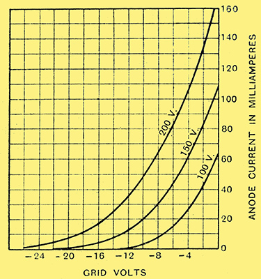
Anode current-grid voltage curves of Micromesh power valve, the P.A.1.
The power valve of the series, which is given the type number P.A.1, has the following exceptional characteristics:-
AC resistance, 1,050 Ω. Amplification factor, 12. Mutual conductance, 12.6 mA/V.
Measured at 100 Volts HT and zero grid bias. Its normal operating conditions an with 200 Volts on the anode and a grid bias of about -11 Volts. which allows an anode current of 40 mA to pass.
Thus, under normal operating conditions the anode dissipation is some eight Watts and the maximum undistorted power output allowing about 5% of second harmonic, is between 1.5 and 1.8 Watts when working into a load of approximately 2,000 Ω The input transformer fitted to present-day moving-coil loud speakers will be found, as a rule, provided with a tapping on the primary winding to give the correct matching between the valve and the loud speaker
Preventing Parasitic Oscillations
The correct value for the grid-bias resistance with the maximum anode potential is 275 Ω, but as this is not a standard size it may be necessary to employ two separate resistances connected in series, the one-Watt type being quite suitable in the present case.
Very low impedance valves, particularly it they possess a high mutual conductance, often generate parasitic oscillations of a very high frequency and result in a considerable increase in the anode current accompanied by a falling off in the power output. However, the inclusion of a small non-inductive resistance of about 100 Ω connected directly to the anode terminal on the valve holder usually suffices to remedy the trouble.
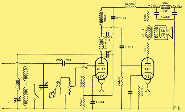
Fig. 1. - Suggested arrangement of detector and output stages using Micromesh HLA1 and PA1 valves.
The complete circuit of a detector and output stage embodying both Micromesh valves discussed here and including suitable values for the various components is given in Fig. 1. Choke-capacity coupling is favoured for the very good reason that, in view of the high amplification of the HLA1, it would seem unnecessary, in all but exceptional cases, to use a step-up ratio LF inter-valve transformer.
The maximum HT available is assumed to be 275 Volts, being the smoothed DC output from the Micromesh R.1 rectifier at the full load of 60 mA. This valve gives full-wave rectification and is of the indirectly heated type, the cathode being connected internally to one end of the heater. There is no mark on the valve indicating to which filament pin the cathode joins, but if the valve holder is mounted so that the anode terminal is on the right hand the cathode connection is the filament pin nearest to the observer. Fig. 2 will, perhaps, make this clear.
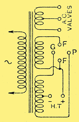
Fig. 2. - Showing connections to valve holder for the Micromesh indirectly heated HT rectifier type R1.
The particular features of interest relating to this valve are that, although it gives an un-smoothed DC output of over 280 Volts at 60 mA., the AC potential on each anode is but 250 Volts RMS, and there are only 15 Volts dropped across the rectifier at full load. The heater requires 4 Volts at 1 Amp., approximately, the supply being obtained from a separate LT winding on the mains transformer.
Micromesh valves will be distributed through the usual channels at BVA prices current for valves of their respective types, but, in addition, arrangements have been made by the Electrical and General Distributors, Ltd., 154, King's Cross Road, London, WC1, to have stocks of all types available for immediate delivery.
|