|
The use of the pentode as a single-valve frequency changer of equal efficiency to that of the conventional two valve arrangement is here described for the first time.
Previous experiments made it abundantly clear that a screen-grid valve was unsuitable for a single-valve frequency changer, and it is obvious that a triode is equally unsuitable. The next step, therefore, was to try out the bi-grid, a four-electrode valve designed chiefly to act as a single-valve frequency changer.
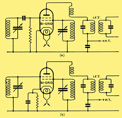
Fig. 1. - The commonly employed bi-grid circuit is shown at (a) and a more efficient arrangement at (b). Circuit interaction is negligible, but the efficiency is low.
A commonly employed circuit is shown in Fig. 1a, and a modified form of greater efficiency in Fig. 1b; the signal input is applied to the outer grid which is biased negatively, in Fig. 1a by the flow of grid current through the grid leak, and in Fig. 1b by the flow of anode current through the cathode resistance. The tunedB; oscillator circuit is connected to bthe inner grid, and reaction is provided from the anode circuit.
Satisfactory oscillation can be readily secured, although a considerably tighter reaction coupling than usual is necessary, and some care is needed in securing freedom from 'squeggering' effects. The efficiency of the arrangement is very low, however, and this is to be accounted for by the low mutual conductance, some 0.25 mA/V, of this type of valve. Circuit interaction, however, is negligible, and in this respect the bi-grid represents a distinct improvement on the triode and screen-grid types of frequency changer.
Having thus found an arrangement which is free from the evil effects of circuit interaction, the reason for this freedom requires explanation; for it is obvious that the valve capacities cannot be greatly lower than those of a screen-grid valve, and the same degree of coupling is to be expected. This is confirmed by measurement, which shows that the outer grid-inner grid capacity is about 9 pF.
The oscillator and pre-selector circuits, therefore, are as tightly coupled as in a screen-grid circuit, and yet circuit interaction is negligible. The explanation of this apparent anomaly is to be found in the fact that in the bi-grid the control grid-anode capacity is of the same order as the control grid-oscillator grid capacity, whereas in a screen-grid valve, the control grid-anode capacity is very much smaller than the control grid-screen-grid capacity.
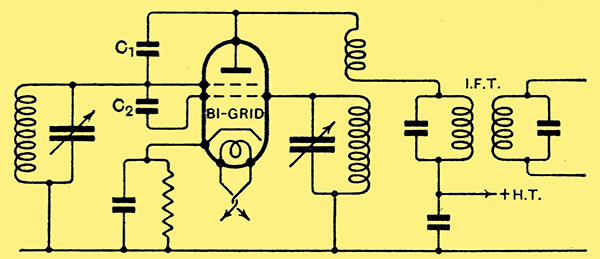
Fig. 2. - The bi-grid circuit re-drawn to show the valve capacities which account for the freedom from interaction.
If the circuit of Fig. 2 be studied, in which the valve capacities are shown at C1 and C2, it will be seen that the potential across the tuned oscillator circuit causes a current to flow through C2, and, therefore, a potential at oscillator frequency to be developed on the control grid. In the anode circuit the same thing happens; the potential across the reaction coil causes a current to flow through C1 and another potential of oscillator frequency to be applied to the control grid.
Now, these two potentials are in opposite phase, so that if C1 and C2 are equal, and the oscillator voltages on the anode and the oscillator grid are also equal, the effective voltage developed on the control grid at oscillator frequency is zero. In other words, the circuit is self-neutralised as regards the oscillator circuits. Even if the capacities be unequal, the neutralising action can be obtained by adjusting the relative value of the oscillator potentials on the anode and oscillator grid. With a screen-grid valve, however, the capacity ratio may be as high as 10,000 to 1, and it is obviously impossible to maintain the balanced potentials in this case. It would, of course, be possible artificially to increase the control grid-anode capacity, but this would give an adjustment difficult to carry out correctly in practice.
Having thus accounted for the freedom from circuit interaction found with the bi-grid, the next step was to find some means of improving its efficiency, for this is very considerably inferior to that of a good screen-grid circuit. To be completely satisfactory, the frequency changer would have to combine the circuit isolation of the bi-grid with the efficiency of the American screen-grid circuit.
Now, from what has been said in this article, it will be obvious that the results depend very largely upon the type of valve adopted, and we are now in a position to postulate the characteristics of the ideal valve. A high mutual conductance between the control grid and anode circuits is the first requisite for efficiency, while approximately equal control grid-anode and control grid-oscillator grid inter-electrode capacities are necessary to secure freedom from interaction. The actual ratio of the valve capacities theoretically required, of course, will depend to some extent upon the mutual conductance between the oscillator grid and anode, and, within limits, the lower this mutual conductance the larger will be the reaction coil required, and the more nearly equal will be the oscillator potential changes on the anode and oscillator grid, and the more nearly equal should be the valve capacities.
The Pentode
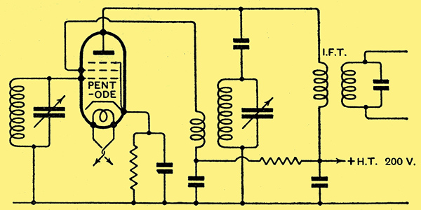
Fig. 3. - The final self-neutralised pentode frequency changer gives negligible circuit interaction, and is as efficient as a screen-grid type. The space-charge grid is operated with a very low positive potential.
The bi-grid is ruled out of count because of its low mutual conductance between the control grid and anode, and the screen-grid valve because of the large disparity in its inter-electrode capacities. A valve with four or more electrodes is essential, and so the only remaining standard type is the pentode, which may be considered as a four-electrode valve for our purposes, as the fifth electrode is connected internally, and is not available for external use.
The high mutual conductance of the pentode is well known, so that on this score it should prove satisfactory. Measurement indicated, moreover, that in certain makes of valve the important inter-electrode capacities were sufficiently alike to prove hopeful. A trial of the valve was accordingly made, and it may be said at once that, when suitable operating potentials were found, the results exceeded all expectations.
The circuit finally developed is shown in Fig. 3, and the Mazda AC/Pen and the Marconi or Osram MPT4 pentodes proved the most suitable; negative bias for the control grid is provided by the 500 Ω resistance in the cathode lead. The tuned-oscillator coil is connected to the anode circuit by a shunt-feed arrangement, with the IF transformer acting as an HF choke and feed capacitor. The steady anode potential is 200 Volts, and the space charge grid, which is used for reaction purposes, is fed from the same 200 Volts supply through a 250,000 Ω resistance, so that its actual operating potential is quite small.
Reaction Coil Resonance
The coil construction is important, owing to the low mutual conductance of the oscillator grid and anode. A very tight reaction coupling is needed to maintain oscillation, but this must not be provided by a large number of turns loosely coupled, for then resonance effects in the reaction coil upset the operation. The reaction coil must consist of a minimum of turns coupled tightly to the tuned winding.
When the oscillator coils are correctly proportioned, this self-neutralised pentode frequency changer is free from the effects of circuit interaction and radiation, so far as normal operation and adjustment will show. Theoretically, of course, it would be necessary to adopt special balancing precautions if the neutralising action is to be maintained over the whole tuning range of the receiver; in practice, however, these are quite unnecessary for all ordinary purposes. In respect of its efficiency, the circuit is equally satisfactory, and, indeed, on this point it is comparable with the American SG circuit.
Although these factors alone would be sufficient to justify the general adoption of the self-neutralised pentode frequency changer in inexpensive superheterodynes, it has still another advantage over screen-grid types, for it is capable of handling without distortion a much greater signal input. In general, superheterodynes demand that an efficient pre-first-detector volume control be fitted to avoid overloading the frequency changer. The pentode frequency changer, however, requires only a moderate amount of signal-input volume control, even on a powerful local. This point alone is of considerable importance, for volume control has always presented a difficult problem to the designer of a superheterodyne, and this has been particularly so in cases where no pre-detector HF stage is to be used.
At this stage of the development it was realised that a single-valve frequency changer had been found which performed as satisfactorily as the more normal two-valve circuit, and that it was cheaper than the two valve circuit. The design of a four-valve superheterodyne, therefore, which should be comparable in cost with, and give a generally more satisfactory performance than, the popular straight three-valve set had been brought within the limits of possibility.
The development of this was proceeded with, therefore, and it may be said that the resulting receiver was found to give a sensitivity rather better than that of a straight three-valve arrangement, while the quality was equally good. The selectivity, naturally, was incomparably better, since it proved possible in the North of London, quite close to Brookmans Park, to receive weak Continental stations working with frequencies separated from those of the powerful locals by no more than 18 kHz.
Although the results with such a four-valve superheterodyne are of an exceptionally high order, naturally they do not quite reach the high standard set by the very ambitious type of superheterodyne with a greater number; of valves, such as the Monodial AC Super. Nevertheless, where neither the maximum of selectivity nor the highest sensitivity are necessary, the four-valve superheterodyne will give a highly satisfactory performance.
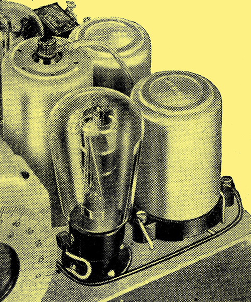
An experimental superheterodyne receiver in which a single-valve pentode frequency changer can be seen in the foreground.
The receiver which has been developed is for AC operation, and includes ganged tuning, pentode output, and built-in moving-coil loud speaker; it will be described in the near future.
|