|
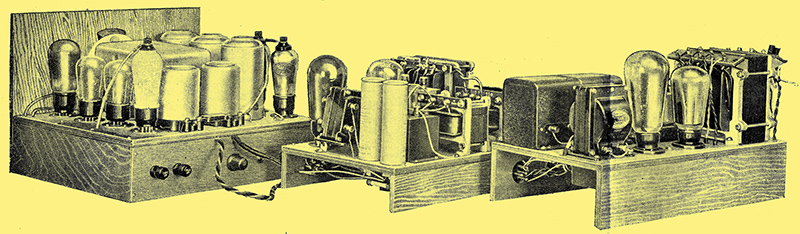
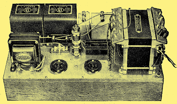
The Monodial AC Super as modified for AVC, together with the two power units.
Fading is one of the chief obstacles to successful distant reception, and any method by which it may be considerably reduced is bound to be appreciated. In the accompanying article appear details of the first constructional set to include automatic volume control which, it can be confidently stated, removes some 80% of the effects of fading.
Part One - Modifications Necessary for Converting the AC Superheterodyne
Since the description in this journal of practical automatic volume control systems, constructors of the Monodial AC Super have been clamouring for details of the modifications necessary for the inclusion of this refinement. The high performance of this receiver has led many to feel that fading, and not interference, is now the chief drawback to distant listening, and that the inclusion of an automatic volume control, would largely overcome this effect, and so increase the number, of stations from which reproduction of entertainment value can be obtained.
The matter has been given very careful attention, therefore, and many practical forms of automatic volume control have actually been tried out in the Monodial, in order to determine the particular type of control most suited to its characteristics. It may be said, briefly, that the square-law [★] Practical Automatic Volume Control. The Wireless World, January 6 and 13, 1933. control has been found to be the best for this set - partly because it can hold the volume at a more nearly constant level than any other, and partly because it fits in best with the characteristics of the Monodial.
No Fundamental Alterations
Some words of explanation may be necessary regarding the course adopted in describing the first practical automatic volume control system as an addition to an existing receiver instead of including it in an entirely new design. In the first place, it is thought that in view of its present unfamiliarity, constructors will be more likely to meet with success in applying it to an existing receiver, which is known to be functioning correctly, than if they have to tackle the problem of getting the system to work in a new and untried set. Secondly, although it is now nearly a year since it was first described, the performance of the Monodial is so far in advance of its time that it is doubtful whether any great improvement could be made to the receiver itself, and, as a result, a new set would vary only in non-essentials. Thirdly, so many of these receivers have been built that it is felt that they should not be rendered in any way out of date by being without this latest development of automatic, volume control.
The actual work of alteration is not great, and, once made, there is no external apparatus. The alterations involve a certain number of additional components, and the rearrangement of some of the existing parts, but it has been found possible to include all the apparatus on the original chassis without increasing their dimensions, so that existing cabinet work remains unaffected.
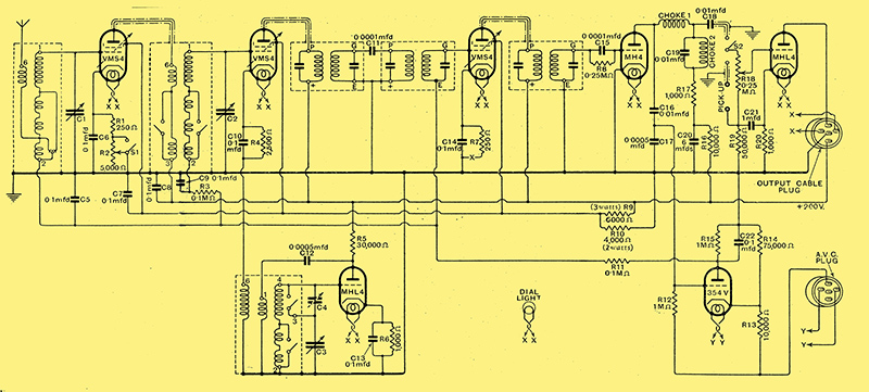
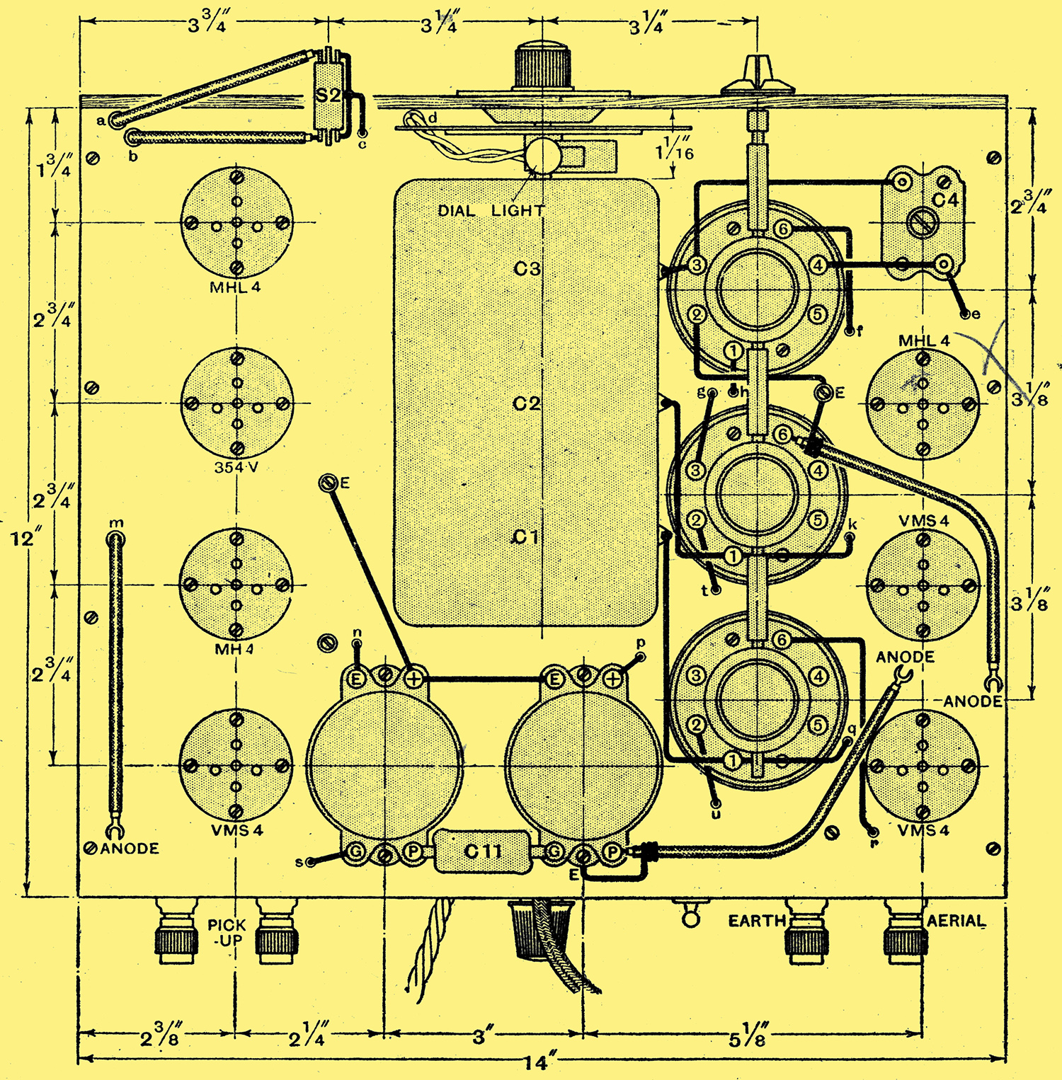
Fig. 1. - Complete circuit diagram of the receiver unit. The 354V valve provides square-law AVC.
The complete circuit diagram of the receiver unit is shown in Fig. 1, and it will be instructive to compare, this with the original circuit [★] The Monodial AC Super. The Wireless World April 6, 13 & 20, 1932. or The Monodial AC Super Booklet. It will be seen that there are no fundamental alterations, and the principle of operation is identical with that of the original receiver. Instead of being connected directly to earth, however, the input and inter-valve tuned circuit return leads are each broken, and these circuits completed through 0.01 μF capacitors C5 and C9. The AVC bias is then applied to the lower ends of the tuned circuits through decoupling resistances.
Each, valve is now independently biased, as regards its minimum value by a resistance in its cathode lead. In the case of the first detector, the resistance R4 is given a value of 2,500 Ω, since a VMS4 variable-μ valve is now employed, and controlled by the AVC system. The IF stage has its minimum bias fixed by the 250 Ω resistance R7, shunted by the 0.1 μF C14, while the same values are employed in the HF stage for R1 and C6 when the switch S1 is closed.
The Noise Suppressor
This switch, which was the Local-Distance switch of the original design, is connected in parallel with a 5,000 Ω variable resistance R2, and both are in series with the bias resistance R1; the actual component used for R2 incidentally, is the volume control of their original set. The purpose of this arrangement is to act as a background limiter, or noise suppressor, while tuning. It will be appreciated that in the absence of a signal, and with S1 closed, the sensitivity of the set is at its maximum and atmospherics and local interference are reproduced at full strength. As soon as a signal is tuned in, of course, the sensitivity drops and the background falls to the normal level found with a set having a manual sensitivity control. When actually tuned to a station, therefore, AVC causes no increase of background, but during the process of tuning such a set is definitely noisier, for the sensitivity rises sharply as the tuning is varied between stations.
The additional bias resistance R2 is included, therefore, so that the maximum sensitivity of the set can be limited on occasion. It is recommended that the switch S1 be opened, and at the start of an evening's listening R2 be adjusted to such a value that the background, with the set mis-tuned from at station is no greater than can be tolerated. Thereafter, only stations which are stronger than the background will come in at full strength, and these, of course, are just those which are worth while from an entertainment point of view. The resistance is made readily adjustable, since the background level, and hence the usable sensitivity, vary from night to night, and the switch is included so that the resistance can be, cut out of circuit in a moment whenever the maximum sensitivity is required, as might be the case when following a strongly fading signal. These two components are fitted, to the back of the chassis, since they require only occasional adjustment, but there is no objection to bringing them to the front panel if desired, provided that screened wire be used for the connections.
In connection with the alterations, it should be noted that the IF transformer secondary feeding the IF valve is no longer returned directly to the chassis, but is taken to the AVC feed. The compensating resistances in the screen feed circuits are now done away with, since they are inapplicable to AVC, their place is taken by a simple voltage divider of fairly low value, and must be remembered that the 6,000 Ω resistance is of the 3 Watts type, while the 4,000 Ω resistance R10 is of 2 Watts rating. Owing to the low values adopted for these resistances, the rise in screen and anode potentials at high bias is limited.
The Second Detector
In the detector stage, the chief alteration lies in splitting the anode-cathode by-pass capacitor into two series capacitors, C16 of 0.01 μF and C17 of 0.0005 μF, from the junction of which the IF feed to the valve is tapped off. The detector is now; worked at rather a higher signal input than before, and its power handling capacity has consequently been increased by reducing the decoupling resistance. R16 yo 10,000 Ω. A 1 Watt resistance can be used, but as there is a 2 Watts resistance available from the original components, this is employed. This decrease in resistance necessitated an increase in the de- coupling capacitor C20 to 6 μF. This capacitor is actually made up of two in parallel: the original 2 μF type BB capacitor, and a 4 μF type LSA previously used in the power unit. In this connection it should be noted that the type LSA is unnecessarily good for this point, and it is only used because it is available from the original components. If entirely new parts are used throughout, a 4 μF type, BB is entirely suitable and cheaper. The LSA capacitor will not be available in a conversion of the Monodial used with the Modern Straight Five power unit, so that in this case also a type BB should be used.
The tone corrector stage remains unaltered, save that the grid circuit is now decoupled by the 50,000 Ω resistance R19, and its grid leak is replaced by the manual volume control, which operative on both radio and gramophone, R18 of 250,000 Ω, and is of the tapered type. Actually, of course, such decoupling is not fully effective in a resistance coupled stage, and the inclusion of the component is more for the purpose of avoiding any possibility of hum due to ripple on the bias resistance than for decoupling proper.
The valve-holder originally used tor the second detector is employed for the AVC valve, and the second detector is now mounted in the place formerly occupied by the third IF transformer. This transformer is fitted beneath the base-board, being mounted skew-wise on the end supporting batten, in such a position that its trimmers can just be operated. The wiring, furthermore, is sufficiently clear to allow the coil can to be removed tor the adjustment of the coupling.
Delayed Action
The AVC valve is the type 354V its anode is connected directly to earth through a 1 MΩ resistance R15, shunted by at 0.1 μF capacitor C22, and the bias voltages are tapped off from the anode and fed to the grids of the controlled valves through the 0.1 MΩ decoupling resistances R11 and R3. The AVC grid is fed directly from the tapping point on the second detector bypass system, and is returned to negative HT, not the chassis, through a 1 MΩ resistance R12. The correct bias to give delayed action to the control is obtained from a tapping on the voltage divider between negative HT and the receiver chassis, made up of the 75,000 Ω resistance R14 and the 10,000 Ω resistance R13. This voltage divider is actually in parallel with the speaker field, so that the voltage drop across this is utilised for the operation of the AVC valve.
In the absence of a signal there is no AVC anode current; there is no voltage drop across R15, therefore, and the grids of the controlled valves are at the same potential as the earth line. As a result, their bias is that fixed by their cathode biasing resistances. When a signal exceeding a certain strength tuned in, rectification occurs in the control valve and anode current flows, its value depending upon the signal strength. A voltage drop is then present across R15, in such a direction as to make the AVC valve anode, and hence the grids of the controlled valves, negative with respect to earth.
The 2.5 Watt-power Chassis
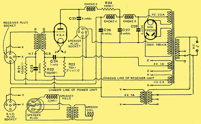
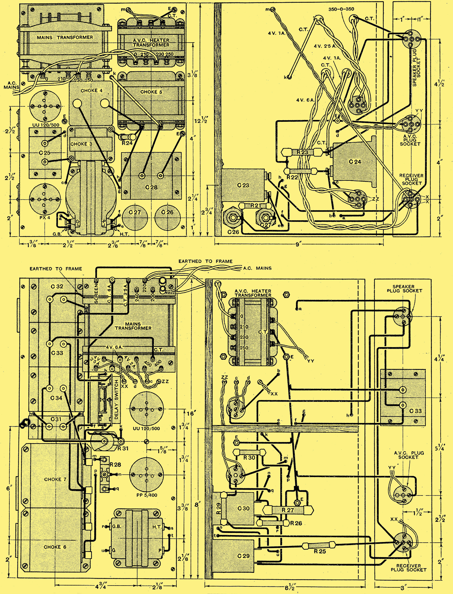
Fig. 2.- In the 2½ Watt power unit the speaker field is included in the negative HT lead.
Perhaps the greatest alterations occur in the power unit, for in order to obtain the voltage needed for the AVC valve the smoothing circuits.have had to be entirely rearranged. The only voltage available is the drop across the speaker field, and so this is connected in the negative HT lead. In this position, however, it contributes little to the smoothing, and it has become necessary to introduce an additional choke. The resistance of this choke must be low to avoid a loss of voltage, and so its inductance is limited, so that considerable increases in the smoothing capacities have also been necessary. The arrangement finally adopted can be seen from Fig. 2; The choke Ch5 is that originally used, but its position on the chassis has been altered, and it has an inductance of some 10 H. at 100 mA, with a resistance of 120 Ω. It is now followed by an 8 μF electrolytic capacitor C27, and the current for the output valve is then tapped off. The remaining 50 mA of current passes through a 30 H 400 Ω choke Ch4, after which there is another 8 μF electrolytic capacitor C26. In connection with this choke, it is important to note that its actual inductance is 30 H, although it is rated by its makers to be only 20 H. It will not necessarily be satisfactory, therefore, to follow the maker's rating, and substitute a different type of 20 H choke.
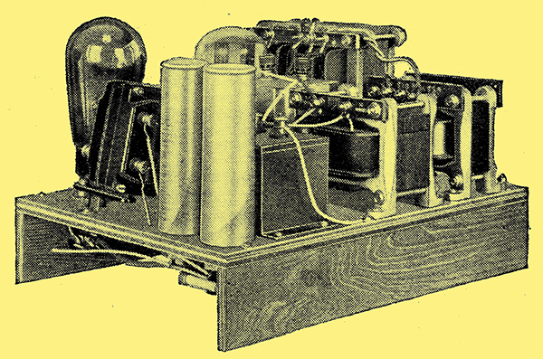
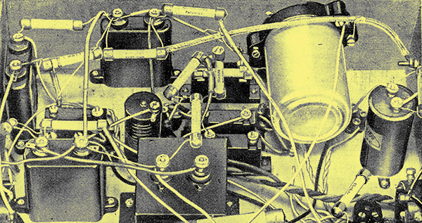
The 2.5 Watts power unit. The electrolytic capacitors can be seen in the foreground and the tilted transformer on the left.
In order to supply the heater of the AVC valve, an additional mains transformer, giving an output of 4 Volts at 1 A has been included. It will be clear from the drawings how room has been found for this component, and the method of interconnection of the two units will also be clear. The original valve-holder and 5-way cable do not give sufficient connecting points for the new arrangement, for three additional leads are required. Another valve-holder is fitted to the back batten of the power chassis, therefore, and an extra 3-way cable makes the connections. Three way cables are not at present available, but a four or five-way type may be used with the unwanted leads cut short.
Part Two - Construction
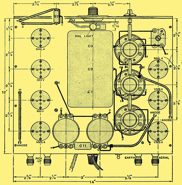
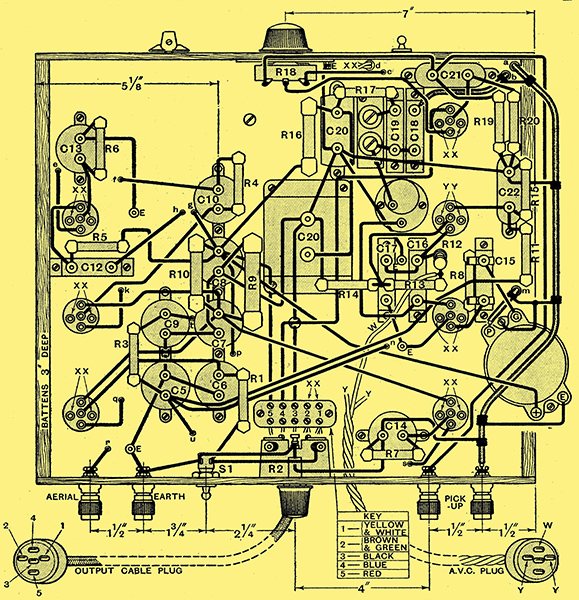
Practical wiring above the baseboard of the receiver chassis.
Details of the alterations to the receiver chassis and the 2.5 Watts power chassis have already been given, and it remains to treat the 5 Watts chassis. This was originally described for the Modern Straight Five [★] The Modern Straight Five. The Wireless World, June 22 and 29, 1932. it will be remembered, but many constructors of the Monodial are using it instead of the power unit described specifically for that receiver. In this case, the conversion is considerably simpler, for there is a higher voltage available. and the speaker field can be retained in the positive HT lead, Where it is fully effective in smoothing. No additional smoothing is thus required, and it is merely necessary to add the additional valveholder for the extra inter-unit cable, the small mains transformer, and to rearrange a few of the connections. The modified circuit diagram of this power chassis is shown in Fig, 3, and the other details will be clear from the drawings.

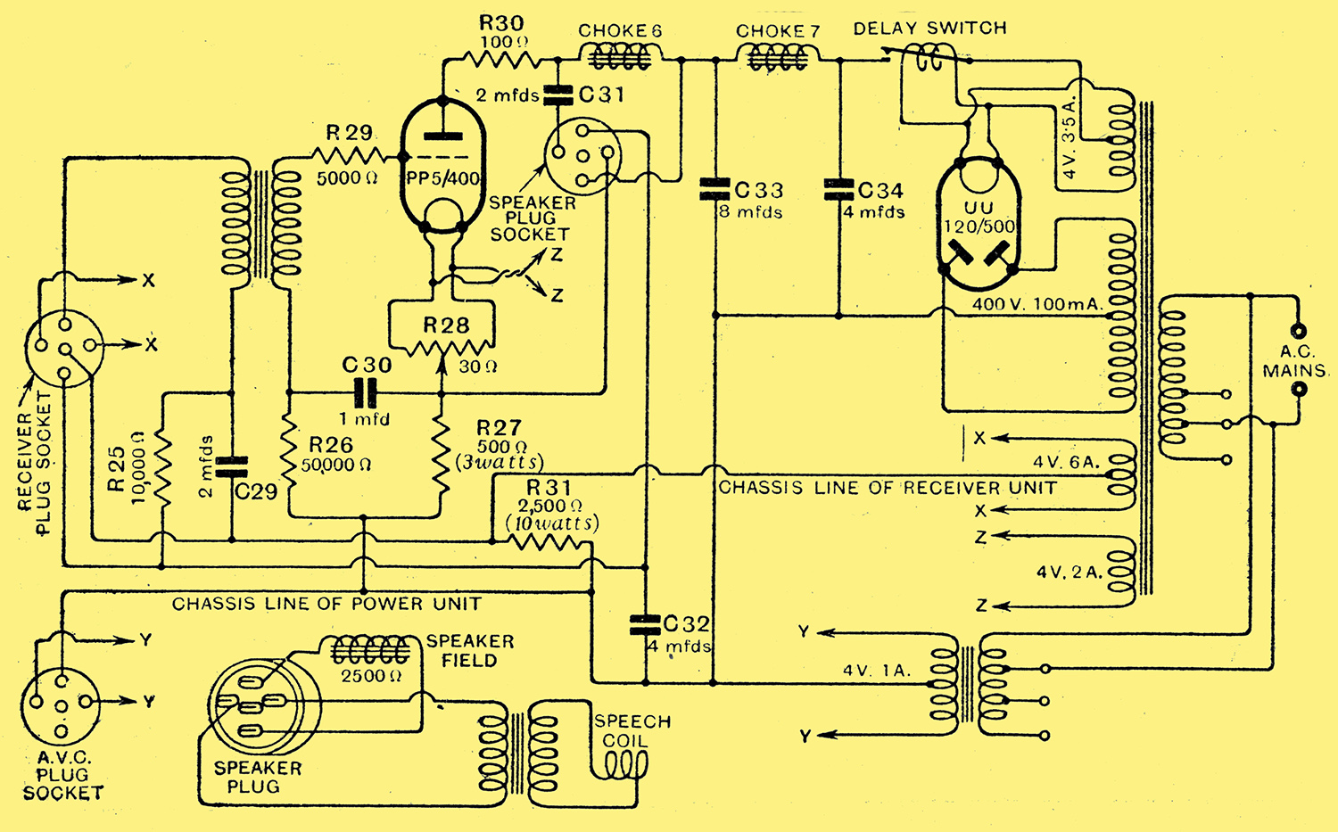
Fig. 3. - The complete circuit diagram of the modified 5 Watts power chassis.
As in the original designs, it is assumed that the field winding of a moving-coil loud speaker will be energised from the power chassis. Where it is not desired to do this, however, a 2,500 Ω 10 Watts resistance must be connected in place of the field in the case of the 2.5 Watts chassis, and a 60 H 60 mA 2,500 Ω choke (suitable types are listed by Scott Sessions and Sound Sales), in the case of the 5 Watts chassis. With this latter unit, it should be noted, sufficient power is available tor energising dual type speakers. These should be each of 2,500 Ω field resistance and one field should be connected to the usual points, while the other is used to replace R31.
The 5 Watts power unit showing the thermal-delay switch.
Re-ganging
The operation of the set is the same which ever power chassis be employed and it must always be remembered that there is a difference of potential of 125 Volts between the receiver chassis and the power chassis. These must not be allowed to touch one another, therefore.
After the alterations have been made, it is highly probable that the receiver will require re-ganging; this must be done. in the manner described in the original articles, but it will now be essential to include a meter as an indicator of signal strength. It is impossible to gang an AVC set without a meter, for the ear can detect no change of volume on operating the trimmers, since this is taken up by the control. The meter used should have a full scale reading of about 10 mA, and be connected in the cathode lead of the IF valve at the point 'X' of Fig. 1 to act as a tuning indicator. In the absence of a signal, it will read nearly full scale - the normal anode current of this stage. When a signal is tuned in, however, it will drop back, and the stronger the signal the greater will be the drop; all trimming adjustments, therefore, must be carried out for a minimum reading on the meter, for this corresponds to maximum signal strength.
In its operation, the control may be relied upon to remove completely the effects of moderate distortionless fading, and, provided that the average modulation depth of the various transmitters is the same. it will hold the volume level approximately constant, regardless of whether the station is distant or a nearby local. The control will, of course, do nothing to remedy any distortion caused by fading, although it will still keep the volume at its normal level. When fading is very severe, it is accompanied by a rise in background noise, and the curious effect is obtained, not of a fading signal, but of a fading background. The control only functions within certain limits, of course, for if the fading be so bad that the field strength drops nearly to zero, the volume will also drop after the set has reached its maximum sensitivity. In general, however, the control may be said to remove 80% of the evil effects of fading.
It should be noted that fading may be followed on the needle of a meter used as a tuning indicator, for the weaker the signal strength the greater the meter reading. In fact, it will often be found that the needle fluctuates greatly without there being any audible indication of fading, such as would be found in an uncontrolled receiver.
Avoiding Hum
Underneath view of a portion of the receiver chassis showing the chief modifications.
A few words about valve types may be of interest. It is recommended that the VMS4 be employed for the three variable-μ stages, and the 164V or MHL4 for the oscillator, although here it is often permissible to employ the 354V, MH4, or AC/HL as an alternative. The second detector can be a 354V, MH4, or AC/HL without altering the results, but if the specified resistance values are to hold, it is important that the AVC valve be a 354V. If the MH4 or AC/HL valves be used instead, it will probably be necessary to change the value of R13, determining the optimum value experimentally, since the current cut-off points of the valves are slightly different.
For the tone corrector, it is recommended that in most cases the MHL4 be used. The exception is where the gramophone pick-up gives only a moderate output, and then the 354V, MH4, or AC/HL should be used without changing any circuit values. The amplification with these latter valves is nearly double, and as a result there is a greater risk of hum, but no trouble from this was found in the experimental model. Little latitude is permissible in the power unit valves.
There is just one point in connection with AVC which is worthy of mention. The level at which the second detector input is held depends upon the capacity of C17. It an incorrect value capacitor be used at this point, therefore, or it the component be widely different from its rated value, the second detector, input will be held at the wrong level. If it be found, therefore, that on all signals the second detector is overloaded, the probability is that C17 has too large a capacity. Conversely, if C17 be too small, the detector output will not be great enough for full volume. Any adjustment should be carried out on the local station, and the value selected should be such that on the strongest station the second detector is just not overloaded.
The under-baseboard wiring of the receiver unit.
One result of fitting AVC to the Monodial is to make the tuning appear flatter. It is not actually so, of course, for all the fundamental characteristics of sensitivity, selectivity and quality are unaltered. The effect is found in all AVC sets, and is due to the rise in sensitivity as the receiver is mis-tuned from a carrier. It is, therefore, more difficult to tune the set accurately to resonance by ear, and it is usually necessary to tune, not for the loudest signals, but for the deepest quality of reproduction. There is no real difficulty in this, and the knack is soon learnt, but there is no doubt that a tuning indicator is a great help, and where the additional cost is not objected to, it is recommended that a meter be permanently wired in the IF cathode circuit for this purpose.
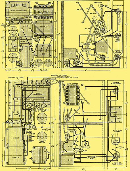
Practical wiring of the 2.5 Watts (above) and the 5 Watts (below) power chassis modified for AVC.
|