|
It has long been known that the ordinary screen-grid valve is handicapped by a secondary electron effect which introduces a kink in the characteristic and thus limits its signal-handling capacity. In the screened HF pentode and the variable-μ pentode about to become available in this country, this disability is avoided and the substitution of the new valves for their SG tetrode counterparts, in both straight sets and superhets, will result in considerable improvement in stage gain and stability.
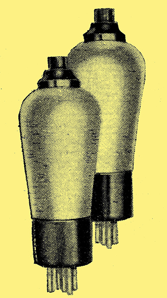
The new Mullard SP4 and VP4 valves - the screened and variable-μ pentodes respectively.
The development of the high-frequency or screened pentode represents a further improvement in high-frequency amplification, and its advantages are not confined to this stage of a receiver.The screened pentode is similar in external appearance and connections to the screen-grid valve, and may be regarded as a development of the screen-grid tetrode rather than the normal LF pentode. By the introduction of an additional grid between the anode and screening grid of the screen-grid valve, the special characteristics of the pentode are obtained. This grid, as in the LF pentode, has the effect of removing the negative resistance kink from the characteristic of the tetrode and also gives an extremely high magnification factor together with an adequate slope.
Advantages Over SG Valve
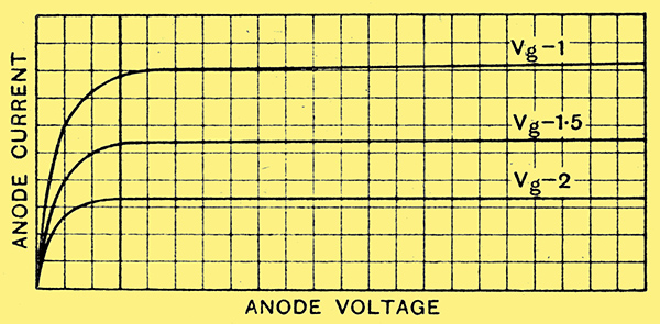
Fig. 1.-Typical characteristic curve of an HF pentode. It will be seen that the negative resistance kink, common to the screen-grid tetrode, has disappeared.
The impedance of the screened pentode is generally considerably higher than that of the tetrode, and consequently the sensitivity of the HF stage will depend very largely on the dynamic impedance of the tuned circuits. This high impedance of the pentode ensures practically unaltered radio frequency characteristics of the associated circuits, and, in addition, if really efficient coils are used, the gain will be very much greater than that obtainable with a tetrode. Even with normal coupling coils, the HF pentode will give improved results over a screen-grid valve.
In spite of its very high magnification factor, the pentode has a grid base equal to that of a normal tetrode, although, in general, where signal voltages of varying amplitude are to be handled, the multi-μ pentode would be used, in the same way as the multi-μ screened grid.
Following the usual practice in high-frequency amplifiers, the multi-μ pentode is preferable to the normal type for both high- and intermediate-frequency stages, as it has the additional advantage of sensitivity control by negative bias variation, and has, at minimum bias, a stage gain equal to that of the normal screened pentode. It is well known that, in the case of the screen-grid tetrode, considerations of secondary emission effects limit the screen voltage to a narrow region. No such restriction exists in the pentode valve, Where secondary emission effects have been eliminated, and by suitable variations in auxiliary grid voltage, wide adjustment of the multi-μ characteristics is possible.
The resistance network required to maintain the auxiliary grid voltage at a constant potential,- irrespective of bias variation, is similar to that for multi-μ tetrodes.
One of the main spheres of usefulness of the screened pentode lies in its application as detector, and particularly as that of first detector in superheterodyne receivers. It can be used quite satisfactorily with any of the circuits already developed for screen-grid valves, and will give improved results with less critical voltage adjustment.
An efficient, though quite simple, circuit arrangement has been developed which takes advantage of the pentode characteristic, a curve of which is shown in Fig. 1. It will be seen that with low anode voltages (such as 30 Volts) on the anode and with normal auxiliary grid and control grid voltages, there is a sharp 'knee' in the characteristic curve, and if the valve is operated just above this point, excellent rectification is obtainable with complete absence of re-radiation.
This method of rectification is not possible with screen-grid valves because the negative resistance characteristic gives rise to dynatron oscillation.
Single-valve Frequency Changer
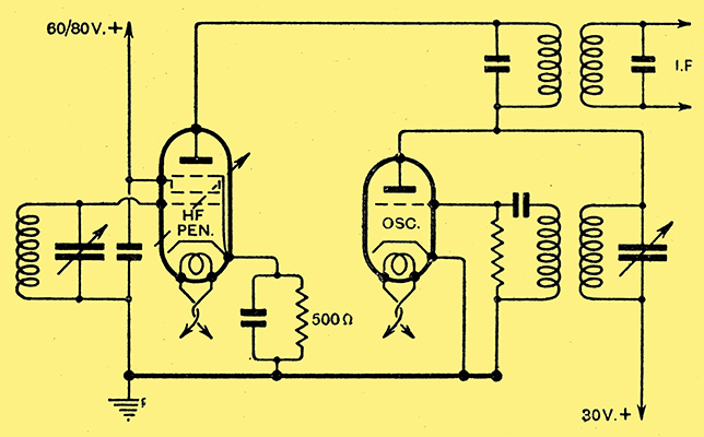
Fig. 2. - Skeleton circuit of a two-valve frequency changer in which the first detector is an HF screened pentode.
Fig. 2 shows a suitable circuit arrangement for operating the screened pentode as a first detector under the above conditions.
A further important use of the screened pentode is undoubtedly its application as a combined oscillator-detector. Although for this purpose the auxiliary grid coupling method can be employed, cathode coupling using a suitably designed circuit is more satisfactory. Using the former method, with the comparatively small coupling coil permitted by the high amplification factor of the valve, re-radiation is less than when using the most suitable LF pentode, previously considered to be most satisfactory in this respect.
The prevalent opinion in this country, that cathode coupling causes excessive re-radiation, would seem to indicate that it was not realised how small the coupling coil could be made while still maintaining sufficient coupling for oscillation. A small coil (of about 5 microhenrys for medium waves) gives extremely satisfactory results, and the re-radiation voltages are considerably lower than those given by any other coupling method. It should be noted that the use of too large a coil may give bad re-radiation.
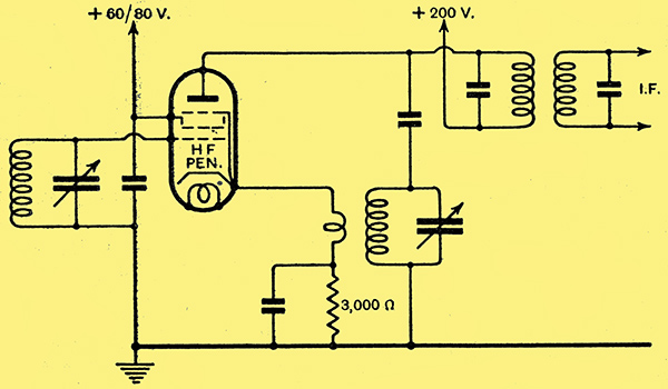
Fig. 3.-The screened pentode as a single-valve frequency changer with cathode coupling.
Fig. 3 shows a circuit arrangement suitable for a cathode-coupled oscillator-detector using a screened pentode.
Used for negative-bend detection, the pentode has the important advantage that larger anode voltage swings are possible than with the screen grid tetrode. As there are no secondary emission effects the maximum anode voltage swing is practically a constant with normal external anode resistances. Due to the very high impedance, sensitivity is practically proportional to the anode resistance chosen, but the usual limitations imposed by the necessity of retaining the higher audio frequencies must be carefully taken into account.
|