|
Practical notes for the new Osram MHD4 Valve
There is no doubt that the double diode triode, in the same way as the variable-μ of two years ago, introduces a new phase in set design. Without the variable-μ the double diode triode would have an extremely limited field of usefulness; without the double diode triode the full advantages of the variable-μ are not realised. The two valves together form a complementary combination with fascinating possibilities particularly in the direction of automatic volume control.
The use of the double diode triode [★] Automatic Volume Control, The Wireless World, February 17, 1933. as a means of providing automatic volume control has recently been described, and it is the purpose of this article to give practical operating data for the first British example of this new type of multiple valve. As the various circuits for quiet, amplified and delayed AVC have already been given, it remains to put forward the detecting and amplifying aspects of the valve.
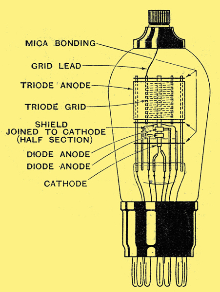
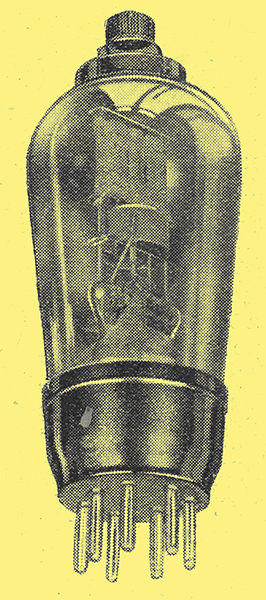
Fig. 1. -The electrode arrangement of the Osram MHD4. The grid connection of the triode is at the top of the bulb and the other electrodes are brought out to a 7-pin B7 base now standardised for multiple valves.
The general layout and construction are shown in Fig. 1. It is seen to consist of a normal triode with the grid connected to a terminal on top of the bulb, and small auxiliary anodes placed round the lower end of the cathode. These auxiliary anodes are very carefully screened from the grid and anode of the associated triode in order to keep the capacities between the two sets of electrodes as small as possible. If this is not done HF voltages or high audio frequencies may be passed through the valve and cause loss of efficiency or bad quality reproduction.
The screening is obtained by shrouding the small anode with a metal cover and, additionally, by taking the grid out at the top of the bulb and thus having no grid lead within the pinch of the valve. In order to accommodate the increased number of; electrode connections in the MHD4 as the new valve is called the new type of seven-pin base which has been standardised in this country for multiple valves will be employed.
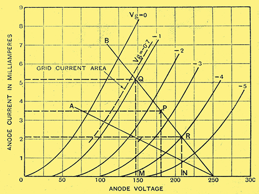
Fig. 2. - Anode Volts/anode current characteristics for the MHD4 valve. Two load lines have been drawn (A) for 50,000 Ω and (B) for 20,000 Ω.
The characteristics of the valve are shown in Fig. 2, average values being as follows: The amplification factor is 40, the AC resistance 16,600 Ω, and the mutual conductance 2.4 mA/Volts, these constants being measured at an anode voltage of 100 and zero grid, volts.
The use of a diode followed by a triode, thus separating the functions of detection and amplification, is now well known. The advantages of this scheme over other forms of rectifier are threefold. First, the input impedance of the diode rectifying circuit is high, secondly, the diode provides nearly perfect rectification, and thirdly, no high-frequency voltages are passed on to the triode amplifying valve. Thus it is able to handle a much larger input than a similar triode used as a grid detector.
The Osram MHD4 comprises diode and triode elements in the same bulb, thus giving increased convenience and decreased cost with no loss in efficiency. Two separate diode anodes are provided in order to render possible full-wave rectification or various different types of AVC circuits.
The advantages of diode detection in giving a linear response are well known. It is not, however, commonly realised that a diode detector imposes very little damping on the preceding tuned circuit. In tact, in this respect, diode detection has only one rival - an anode-bend screen-grid detector. This latter rectifier is only of practical utility when it is of the self-biased type, and even then it is non-linear for small inputs.
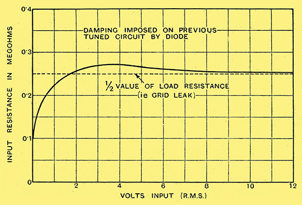
Fig. 3.- Damping imposed on preceding tuned circuit by one diode.
Fig. 3 shows the effective input shunt resistance of one diode of an MHD4 valve, measured by the damping produced on a tuned circuit connected across the input. In this case the load resistance (corresponding to the grid leak in the case of a triode valve) was 0.5 megohm, and it will be seen that, except for very small inputs, the damping produced by the diode valve is approximately 0.25 megohm for a diode load resistance of 0.5 megohm. It can be shown theoretically that, for large inputs, the effective input resistance of a diode rectifier circuit is one-half the value of the load resistance. The effective input resistance of the MHD4 valve does not at any time fall below 70,000 Ω, and only reaches this minimum value for very small inputs.
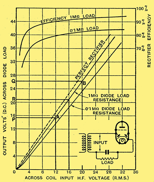
Fig. 4. - Rectifier characteristics of the MHD4 valve operated in a half-wave circuit.
Figs. 4 and 5 give the rectifier characteristics of an MHD4 valve operated as a half-wave rectifier and as a full-wave rectifier, using either one diode or two diodes in parallel. As an example in the use of these curves, consider a single diode rectifier with a 1 megohm load resistance and an HF input of 16 Volts carrier, modulated 25%. Thus the HF input swings between the voltages 12 and 20, and the working point moves between A and B, giving a peak LF output developed across the load resistance (½ voltage PQ) of 5.4 Volts. The DC bias available for AVC purposes is represented by the point R, or 20.8 Volts. It will be seen that greater efficiency and linearity are to be obtained when using a 1 megohm load resistance, but this gain is only obtained at the expense of some high-note loss, owing to the larger time-constant of the load resistance capacitor combination. The use of an 0.5 megohm load resistance is recommended with the MHD4.
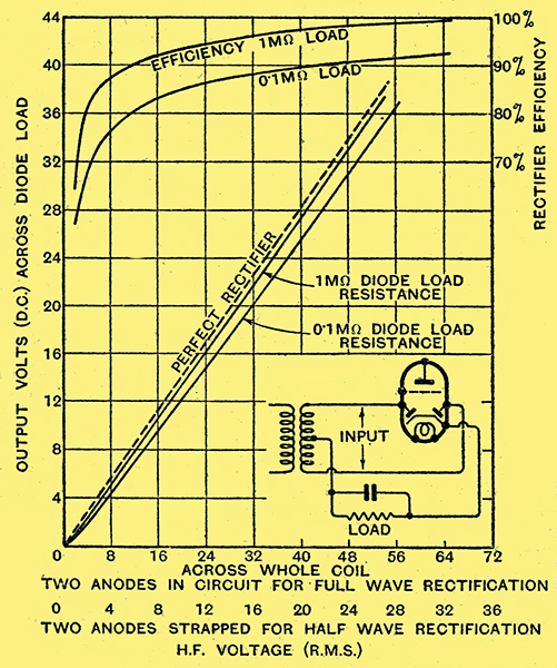
Fig. 5. - Rectifier characteristics when both diodes are used.
Leaving the question of rectification behind, we have to consider the most effective way of utilising the triode of the MHD4 in order to obtain faithful reproduction and the necessary overall sensitivity, together with any AVC action which may be required.
Amplified AVC
To obtain this performance the following three factors must be carefully considered: the value of the anode load resistance, the value of the auto-biasing resistance, and the output obtainable from the valve. The signal handling capacity of the valve must not be forgotten, and special attention must be paid to this point if amplified automatic volume control is to be used. These points can be determined directly from the anode voltage / anode current characteristics of the valve which are shown in Fig. 2 for several values of grid voltage. Two load lines have been drawn (A) for a 50,000 Ω resistance load and (B) for a 20,000 Ω ohm load, assuming an HT supply of 250 Volts in each case.
Taking line (B) as an example, it can be seen that a grid bias of 2.5 Volts will bring the working point of the valve to P. If a 1.5-Volt peak value audio frequency is applied to the grid, the grid potential will vary from Q to R, and the voltage across the output load from M to N. This represents 62 Volts; therefore the output will be 31 Volts peak.
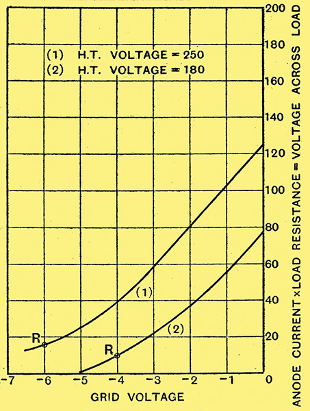
Fig. 6. - Graph showing variation of voltage across anode load resistance with change of grid voltage. Curve (1) is taken at 250 Volts HT and curve (2) at 180 Volts.
In the case of the 50,000 Ω load the maximum output becomes 37 Volts-peak. If amplified AVC is being employed no biasing resistance is required, for the grid bias on the triode is supplied by the rectified radio-frequency signal, and is, in fact, approximately equal to the peak value of the signal applied to the detector. In practice, the bias will vary from 0.7 Volts to 5 Volts, and if distortion is to be prevented care must be taken to ensure that anode-bend rectification does not take place. This may occur with large signals unless the DC voltage across the load resistance in the anode circuit is more than 2.5 times that required for full AVC action. This point is illustrated in Fig. 6, which shows the relation between grid volts and anode current with a 20,000 Ω load resistance in the anode circuit. If appreciable distortion is to be prevented the grid must not be allowed to run more negative than point R on the curves. The steady bias on the valve should not exceed half the value corresponding to R, or, if it does, care must then be taken not to apply too large an audio frequency signal to the grid.
For large signals sufficient output is obtainable to drive a pentode (PT4 or MPT4), or even a power triode (PX4) directly off the MHD4 by means of resistance coupling, but if the set is not very sensitive or has not a very large range of AVC control, then it may be advisable to employ a parallel fed transformer coupling. A suitable circuit for this is shown in Fig. 7.
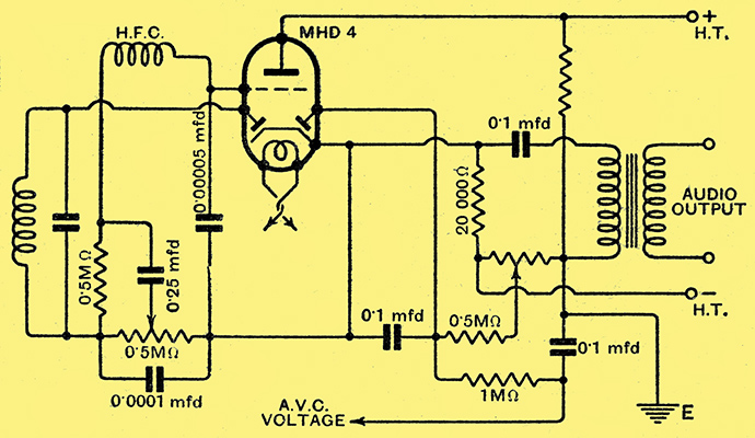
Fig. 7. - The double diode triode may be coupled to the output valve of the receiver by means of a parallel-fed transformer when the range of AVC control is not very large.
When simple AVC is employed the audio frequency voltage obtained across the anode resistance is ample to load a PX4 fully without a transformer coupling, due to the higher radio-frequency amplification which is employed in this type of set. From the foregoing it will be seen that the MHD4 has fascinating possibilities.
|