|
Although the output transformer is often neglected, it can exercise a profound effect upon the performance of a receiver in regard to the quality of reproduction. In this article, constructional details are given of a push-pull component designed especially for the New Monodial Super.
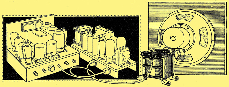
The choice of a suitable output transformer is a matter requiring a no less care than the selection of an inter-valve coupling, if the best reproduction is to be obtained. The output stage is designed to work with a definite value of load impedance - in the case of the New Monodial Super it is 10,000 ohms - but it is rare to find that the loud speaker has the precise value required. The two are joined together, therefore, by means of a transformer with its ratio so chosen that the effective impedance of the speaker is altered to the necessary degree. Thus, the speaker may have an impedance of only 1 Ω and the output stage may require a load impedance of 10,000 Ω, but the use of a transformer of 100:1 ratio will result in the equivalent of a 10,000 Ω speaker with a 1:1 ratio transformer.
The question of ratio does not enter into the choice of primary inductance for the transformer, and we can consider the primary as a choke in shunt with the load impedance. Since the reactance of a choke falls with decreasing frequency, it is obvious that the efficiency of transformation will fall at low frequencies. It can be shown that the loss of bass due to this is small if the choke reactance is not lower than the load impedance at the lowest frequency required, but this is not all. As the load and the primary must be considered to be in parallel, the effective load impedance of the output stage falls as the frequency decreases, with the result that the maximum undistorted output obtainable also drops. There is thus a risk of amplitude distortion arising at low frequencies through the use of an output transformer with an inadequate primary inductance.
The Transformer Primary
If this effect is to be negligible, a higher primary inductance is required than is necessary merely for the maintenance of an even response curve at low frequencies, and in general the primary reactance should not be less than twice the load impedance at the lowest frequency required. For a 10,000 Ω load and a low frequency limit of 50 Hz, this means a primary inductance. of some 63H or more.
The next point of importance is the power rating. It is more a question of the AC Volts developed across the primary at the lowest frequency than of actual power, however, and with a 10,000 Ω load and a 6 Watts output we must allow for a maximum potential of 245 Volts across the load impedance. The flux density in the core must not be allowed to exceed a certain figure if amplitude distortion is to be avoided, and it is dependent upon the quantity of iron, the number of primary turns, the voltage developed across the primary, and the frequency. For a given voltage and frequency there is a minimum quantity of iron and number of turns which must be used if distortion is to be avoided.
Both primary and secondary resistances must be low if the general efficiency is to be high, and an appreciable proportion of the power delivered by the output stage is not to be lost in the transformer. In theory, maximum efficiency will be secured for a given winding space and number of turns when the secondary resistance is equal to the primary resistance divided by the square of the turns ratio. In practice, however, it is usual to make the secondary resistance rather higher than this for two reasons - because the primary resistance causes a loss of anode voltage on the output stage, and we like to keep this as small as possible, and because when a high ratio is used the secondary wire gauge demanded by theory is apt to become unwieldy. With any reasonable choice of wire gauges the resistance losses are very small.
Leakage Inductance

The method of winding can clearly be seen from this drawing of one of the bobbins. The other bobbin is identical save for the direction of winding.
One of the most important points is the question of the leakage inductance, for this governs the high frequency response, and if it be large there will be a loss of high notes. For a given method of winding, the larger the primary inductance the greater the leakage, so that if we aim at perfection in the bass we run a risk of losing the upper register. Obviously, therefore, we cannot afford to make the primary any higher than is strictly necessary. The leakage inductance, however, is not governed merely by the primary inductance, but it depends very largely upon the physical disposition of the windings, and by properly interleaving the primary and secondary it may be kept at a low value. The self-capacity of the windings is fortunately of no practical importance, and a high self-capacity is beneficial rather than otherwise.
It will be seen, therefore, that the choice of an output transformer is a matter of some importance. The primary should be selected according to the output stage with which it is to be used, and the turns ratio according to both speaker and output stage. If the speaker be changed at any time the secondary winding must be appropriately altered, but if a different output stage be employed, then it is to the primary that modifications must be made. In designing a transformer for the New Monodial Super, another factor enters owing to the use of push-pull, for this necessitates a centre-tapped primary and a symmetrical disposition of the windings. Fortunately, however, the absence of a direct current through the primary renders the use of an air-gap in the core unnecessary, so that fewer turns and at smaller core can be used than if the transformer were for a single output valve.

The upper portion of the diagram shows the connections between the windings and the terminals, while the lower gives the speaker connections.
The arrangement of the windings can clearly be seen from the drawings. Two identical bobbins are used, each carrying one-half of the primary and one-half of the secondary, and the total primary turns on each bobbin are 2,400. No. 36 gauge DSC wire is used for the primary, and on each bobbin all windings are in the same direction. The two bobbins as a whole, however, are wound in opposite directions, so that the two extreme inner ends of the primary are for connection to the anodes of the output valves, and the two extreme outers are joined together for the centre-tap. Complete symmetry is thus readily obtainable. The secondaries are connected either in series or parallel, according to the ratio required; in the series connection the two-outers are joined together, and the speaker connected to the two inner ends, but in the parallel connection the outer of one winding is joined to the inner of the other, and the outer of the latter is taken to the inner of the first, the two ends thus formed being taken to the speaker.
It is unnecessary to make any attempt at a layer winding for the primary, and it will suffice if the turns are run on as evenly as possible, so that a good surface is maintained for winding the secondary. After winding 1,200 turns a layer of Empire tape should be wrapped round it for insulation purposes, and the secondary can be put in place. Here an even layer winding is essential on account of the thickness of the wire; the turns should be run on evenly and tightly, but in spite of this there will usually be a tendency for the winding to assume a circular rather than a square shape. After the secondary is completed, therefore, the winding should be gently tapped down with a hammer and a block of wood. Another layer of Empire tape should be placed round the winding, and the outer primary section of 1,200 turns can be wound. The second bobbin should be identical with the first, save that all windings should be in the opposite direction.
During winding the formers should be mounted between stout end cheeks to prevent any tendency for the former to collapse; a small winding machine fitted with a revolution counter is a great help, but not strictly necessary. Owing to the fine gauge of wire used for the primary it is a wise plan to solder a short length of heavier wire to the ends for leading out.
The Secondary
Where both secondaries are normally paralleled, one-half the ratio will be obtained by joining them in series, and it will be suitable for matching a speaker of four times the normal impedance. Thus, the 7(0.7:1 ratio with paralleled windings for a 2 Ω speaker will give a ratio of 35.35:1 when the secondaries are connected in series and will then match an 8 Ω speaker.
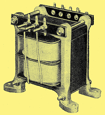
When the coils are completed the bobbins should be placed together and the core inserted. The T and U pieces are inserted alternatively on opposite sides in the manner of a mains transformer, and when the core is completely filled the end plates can be loosely bolted in place. The core should then be gently tapped home with a hammer, and the clamping bolts finally tightened. Small strips of insulating material carried by the ends of the clamping bolts serve for the terminal blocks, and the method of connection should be clear from the drawings.
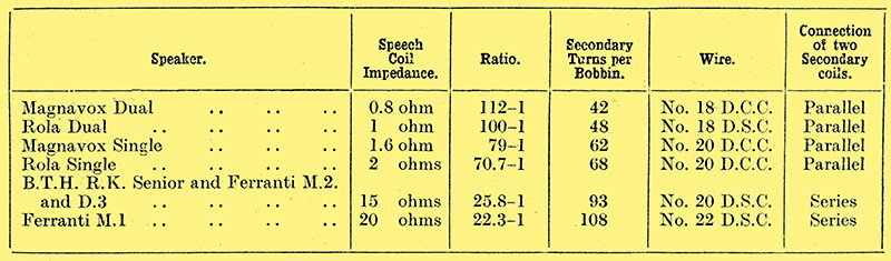
The accompanying Table shows the number of secondary turns, the gauge of wire, its insulation, and whether the coils are to be connected in series or in parallel, for a number of loud speaker types in more common use. The component illustrated was built to have a ratio of 112:1, and gave a measured primary inductance of 69 H; the total primary resistance was only 300 Ω, so that with push-pull valves taking 40 mA a piece the anode voltage is reduced by some 6 Volts only.
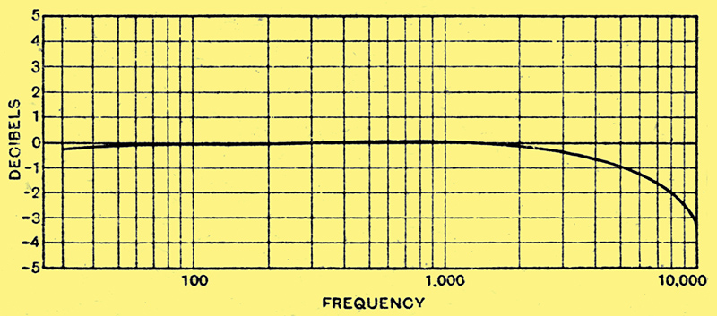
The measured response curve for a 112:1 ratio transformer; the loss at 30 Hz is less than 0.5 dB and at 8,000 Hz it is only 2 dB.
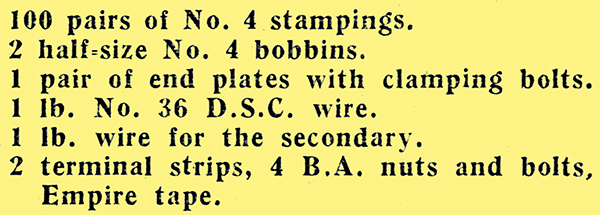
The response curve has been measured, and is illustrated here; it will be seen that it is level within 2 dB over the 50 Hz to 8,000 Hz range, and by extrapolation it can be seen that the useful frequency range is considerably greater for a drop of 5 dB is probably inaudible. The materials necessary for constructing the transformer are quite few in number, and consist of:
The transformer iron, bobbins, and end plates employed in constructing the experimental model were supplied by Sound Sales, who would doubtless supply the transformer completely assembled to special order.
Although designed specially for the New Monodial Super, this component may be employed with any apparatus fitted with a similar type of output stage.
|