|
Combined detector, AVC and output valve.
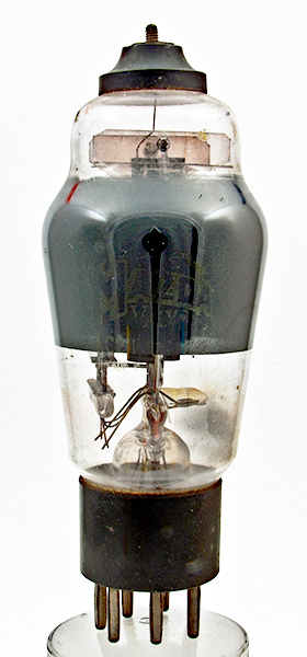
The AC2/PenDD in the museum.
The diode detector has certainly conferred many benefits upon the modern receiver, among which must be numbered distortionless rectification, a simple means of providing AVC and an input load so small in magnitude that the preceding tuned circuit is but lightly damped. It is seldom, however, that such a formidable list of advantages is not accompanied by a disability in some other direction.
The diode cannot amplify and as a result it has hitherto been found necessary to employ an intermediate LF stage, so that there shall be sufficient grid swing to load up the output valve. For convenience of wiring and to conserve space, two diodes - one for rectification and the other for AVC - are usually mounted in the same bulb as the intermediate LF valve, and we then have the familiar duo-diode triode or duo-diode pentode.
There has now been introduced a duo-diode valve - the Mazda AC2/PenDD - in which the rectifying diode is arranged to feed an output pentode directly, without any intermediate LF stage. The valve is, in fact, a duo-diode output pentode having the remarkably high slope of 8 mA per volt, the amplifying portion being identical with the AC2/Pen. The sensitivity is of a high order, since an undistorted output of about 3,400 milliWatts is obtained for a grid swing of 3.4 Volts (RMS).
The more important characteristics are given in the attached data-sheet (here), from which it will be seen that the heater current is twice the normal value, namely 2.0 Amps. There is a standard B7 7-pin base and top control grid contact, the total number of connections to the valve being the same as those of only one of the two valves which it replaces.
It is due to the advent of this valve that a number of manufacturers are now putting on the market a three-valve superhet. In such a receiver the first valve is a frequency-changer followed by a variable-μ HF pentode in the IF stage which, in turn, is linked to an AC2/PenDD. Such a set is capable of a good performance as regards AVC action and sensitivity.
How to Use the Valve
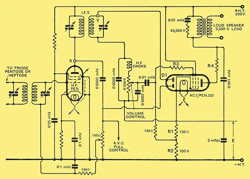
Circuit diagram of the new double-diode output pentode valve. The diode D1 feeds the output stage direct without the customary intermediate LF stage.
The circuit advocated for the AC2/PenDD is given above and shows the popular scheme of half-wave diode rectification with delayed AVC, the delay voltage being equal to E (about 9 Volts), that is the total pressure developed across R1+R2, whilst the bias for the pentode depends upon the volts across R1 only, through which flow the anode and screen current (about 38 mA.). To prevent parasitic oscillations a resistance, R3 or R4, of 50 Ω should be attached directly to the anode or grid terminal of the valve holder and, to filter away from the mains equipment the last trace of HF, a 0.001 μF. capacitor is shunted between anode and cathode of the pentode. An impedance limiter is connected across the speaker transformer primary and the HF choke (which must have an inductance of about 300,000 μH) is found to give the best results when joined in series with the diode load; as shown in the diagram, and not in the potentiometer slider circuit. The delay diode load is tapped so as to give a slightly reduced AVC control to the IF valve while the early stage is fully controlled. An important feature which on test is found to minimise considerably the 'sideband screech' which results from listening to an AVC set slightly mis-tuned from resonance point is the connection of the delay diode to the primary, and not to the secondary, of the IF transformer. The point X is less selective than the point Y.
Attention has been paid to the inter-electrode capacity of the valve owing to the dangers of high-note attenuation duo to Miller effect. To derive the greatest benefit from this, all wiring connected to grid and anode should be short and of low capacity to other leads.
|