|
Constructing distortionless equipment.
The attainment of high quality reproduction demands the closest attention to detail in design both in the choice of circuit and in the selection of the values of components. The amplifier described in this article is exceptionally free from all forms of distortion and is suitable not only for the high quality reproduction of broadcasting and gramophone records, but also for many television purposes. For gramophone work, a special feeder unit is also described, and the use of the apparatus on radio will be covered.
Some of the chief requirements of an LF amplifier suitable for the highest quality sound reproduction were discussed here, and it will be remembered that push-pull amplification offers very decided advantages over other systems, for it permits amplitude distortion to be greatly reduced. Resistance-capacity inter-valve coupling is also desirable, partly because there is little limit to the economical response at low frequencies, partly because the coupling itself is inherently linear and cannot introduce amplitude distortion, and partly because this coupling gives a minimum of phase distortion_an important point in television work.
The question of the power output required for the highest quality is a matter of some importance, and experience indicates that about 4 Watts are needed for domestic purposes. As this figure will appear excessive to many, some explanation may be advisable. In the concert hall the volume of sound from a large orchestra may vary over a range of some 60 dB from the weakest passage of music to the loudest. In broadcasting such a. wide range cannot be permitted, for either the loud passages would cause over-modulation or the weak would be below the inevitable slight background noises. It is usual, therefore, for the range of modulation in the transmitter to be kept within 30 dB. Now 80% modulation is the highest normally used in this country, and 30 dB. represents a voltage ratio of about 31.6:1. If the maximum modulation is 80%, therefore, the minimum is 80/31.6 = 2.52%. It is difficult to arrive at a figure for the average modulation depth on a normal musical item, but for our present purposes it will be sufficient if we assume that the weakest sounds are as much below the average as the loudest are above it. This means that the average modulation depth is 15 dB higher than 2.5%, or 14.2%.
If we employ an output stage capable of delivering 4 Watts to the loud speaker and we adjust the circuits correctly so that this output is obtained on the loudest passages of music, equivalent to 80% modulation in broadcasting, we shall have an output of only 0.004 Watt, or 4 milliWatts, on the weakest passages. On the average level the output is 126.5 milliWatts. An output of this order is easily obtainable from a small battery valve, and such a valve will give good results on the average level of music. It will be hopelessly overloaded on loud passages, however. An output stage rated for 4 Watts, therefore, is necessary for the highest quality reproduction, not because the average volume must be set at a high level, but purely to avoid overloading and distortion on loud passages. If for any reason the volume is required to be unusually great, then the output must be higher than 4 Watts if quality is to be maintained unimpaired.
No amplifier is completely free from amplitude distortion, and opinions, differ as to the amount which can be tolerated. It is usual to rate the output of a triode valve for a figure of 5% second harmonic distortion; and this appears satisfactory for ordinary practice. For the highest quality, however, the distortion should be lower, and as every stage introduces some distortion, that introduced by the output stage cannot be allowed to approach 5%. Under these circumstances push-pull operation is the most satisfactory and economical arrangement, and curves illustrating the performance of this amplifier were given in the article High Quality Amplification. They are reproduced below for convenience.
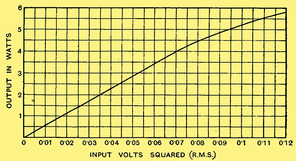
this curve shows the relationship between the square of the input voltage to the amplifier and the power output. it is a straight line for outputs up to 4 watts, indicating distortionless amplification. the distortion at 6 watts, however, is quite small.
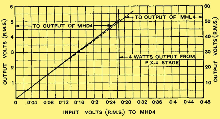
One curve indicates the input output characteristics of the first amplifier stage, while the other gives the same information for the first two stages together. Both curves are straight lines for inputs below 0.265 Volt RMS.
The Frequency Response
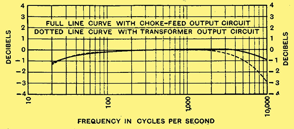
Fig. 2. - The overall frequency response of the amplifier and feeder unit is shown by the solid line curve. At 20 Hz the response falls by only 1.2 dB and at 10,000 Hz by only 1 dB. The response with an output transformer included is shown by the dotted curve, and at 10,000 Hz the drop is under 3 dB - a deviation so small that it is inaudible. .
As regards frequency distortion, conditions are much simpler, and it will suffice if the overall response curve is flat within about 5 dB over the range of 30 to 10,000 Hz, for the ear cannot readily detect small changes of volume at different frequencies. The requirements for television, however, are more stringent, and the 30-line transmissions theoretically require an amplifier flat from 12.5 Hz to 13,000 Hz. In practice, however, an upper limit for even response of 10,000 Hz is very satisfactory, particularly if the cut-off beyond this frequency is gradual and not sudden. Phase distortion, although of little moment in sound reproduction, is important in television. Fortunately, we need not give it special consideration in this case, for with an uncorrected resistance-coupled amplifier it is at a minimum when frequency distortion also is at a minimum. The small degree of frequency distortion found in the complete apparatus is well brought out by the curves of Fig. 2. The full line curve shows the response of the amplifier with a feeder unit containing a duo-diode-triode valve, and the dotted line shows the effect of including the output transformer. The response at as low a frequency as 20 Hz in only 1.2 dB below normal output, and at 10,000 Hz the loss in the amplifier is under 1 dB even including the output transformer the loss at 10,000 Hz is below 3 dB.
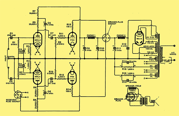
Fig. 1. - The complete circuit diagram of the amplifier shows that two stages of resistance-coupled push-pull amplification are employed. The undistorted output is 4 Watts, but an output of up to 6 Watts is available before the distortion exceeds the value found in normal apparatus. Valves: MHL4, PX4 & MU14
The Push-Pull Quality Amplifier fulfils the requirements of the most exacting, and it is suitable for high quality sound reproduction of both broadcasting and gramophone records, and it may also be used in the reception of 30-line television whether a neon tube, Kerr cell, or cathode-ray system be employed. The circuit diagram of the amplifier proper appears in Fig. 1 and it should be understood that the feeder and output circuits adopted will vary according to the use to which the amplifier is to be put. This will be dealt with in detail later, however.
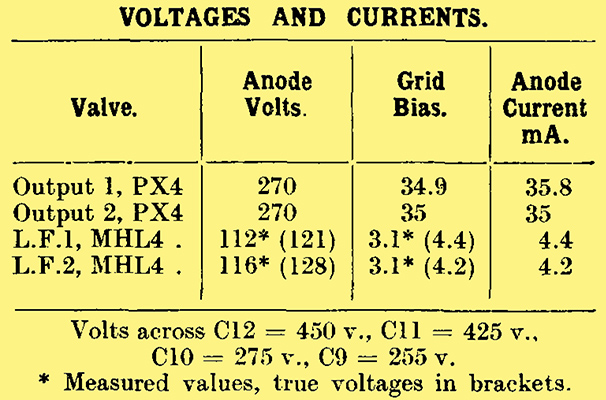
The amplifier is essentially two resistance-capacity coupled amplifiers to which the inputs are applied in opposite phase, and the outputs also joined with a phase reversal thus giving push-pull operation, and a balancing out of second harmonic distortion. The output stage consists of two PX4 valves in push-pull, and to prevent parasitic oscillation the usual grid and anode stopping resistances are included. Each valve is independently biased by the voltage drop along the 1,000Ω resistances R15 and R16 in the cathode circuits. The valves are operated under slightly different conditions from the maker's rating, which calls for an anode supply of 250 Volts and grid bias of -33 Volts, giving an anode current of 48 mA. for each valve. Actually an anode potential of about 250 Volts is used, but the grid bias is increased to -35 Volts, at which the anode current for each valve is 35 mA. It should be understood that these figures are nominal and may vary somewhat with different valves.
Valve Handling Capacity
A push-pull output stage under these conditions is quite linear up to about 4 Watts output when operated, with a total load impedance of 10,000Ω. This load is higher than the maker's figure, and is the change 'brought about' by the different value of grid bias used. The total anode dissipation of the two valves is 17.5 Watts, and .for the true undistorted output of 4 Watts the efficiency is 22.9%, which is unusually high for the very low degree of amplitude distortion which is introduced. A single PX4 under the rated operating conditions gives an output of 2.5 Watts for a dissipation of 12 watts an efficiency of 20.8% and this is for 5% distortion, which is greater than in the push-pull case.
The output stage can. accept an input of 35 Volts peak per valve, or 70 Volts total, so the previous stage must be capable of an output of this order without distortion. No single valve is suitable with resistance coupling, so that a pair of MHL4 valves in push-pull is used. With the values of components selected the stage gain is 9.86 times, so that the total input to these, valves is 70/9.86 = 7.1 Volts peak; the input to each valve, therefore, is 3.55 Volts peak. In the case of output valves it is unwise to use a high value of grid leak, and 250,000&Omega is considered about the safe maximum. For the proper reproduction of the lower frequencies, therefore, a fairly large coupling capacitor has been chosen, and a value of 0.1μF is used. Very high insulation resistance is important in such capacitors, otherwise the grid of the following valve may take up a positive potential, with disastrous results to valve life in the case of an output valve. Although they are fairly expensive, therefore, mica dielectric capacitors have been chosen for use in the couplings to the output valves, for they give a higher factor of safety than paper types. For the couplings to the MHL4 valves, however, paper capacitors are used, since the results of a leakage would not be so serious at this point. Any leakage would still result in a positive bias being applied to the valve, of course, and would upset its operation. It is not so likely to have a. harmful effect on the valve, however, since the high resistances in the anode circuit severely limit the possible anode current.
Before proceeding to a discussion of the various input and output arrangements, it may be as well to deal with the mains equipment. The mains transformer is rated to deliver 425-0-425 Volts at 120 mA. to the MU14 indirectly heated rectifier, which gives an un-smoothed output of 450 Volts at 120 mA. A winding of 4 Volts 2.5 Amperes is provided for the rectifier heater, two of 4 Volts 1 Ampere for the two output valves, and one of 4 Volts at 7/8 Amps for the two MHL4 valves and up to five other valves in early stages which may or may not be used, according to circumstances.
The Smoothing Circuits
The reservoir condenser C12 has the usual value of 4 μF, and preliminary smoothing is effected by an 8 H choke with a resistance of 215Ω, followed by an 8 μF electrolytic capacitor C11. The current then passes through a further choke or a speaker field having a resistance of 1,250 Ω and an inductance of some 25 Henrys or more, the smoothing being effected by the combination of this with the 8 μF; capacitor C10. The drop across this is 150 Volts, or a total drop with Ch2 of 175 Volts, leaving 275.5 Volts for the output stage. There is a small drop in the output transformer primary, but this may be ignored, so that the 275 Volts is split for the anode and bias supplies for the output stage.
At this point the current for the output stage is tapped off and the remaining current of 50 mA passes through the 20 Henry choke Ch1, where further smoothing takes place in conjunction with C9. This choke has a resistance of 400Ω, so that there is a drop of 20 Volts across it, and a supply of 255 Volts is available. The MHL4 valves are fed from this point and take about 4.3 mA apiece, so that some 41 mA is available for operating a radio receiver.
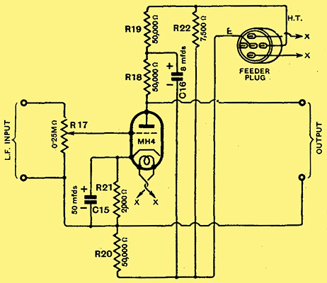
Fig, 3 - The circuit of the feeder unit which is needed only for gramophone work. The input is applied to the valve in the usual way, but the output is split across R18 and R20 for feeding the amplifier in the correct phase.
Turning now to methods which may be used for feeding the amplifier, several alternatives present themselves according to the use to which the amplifier is to be put. For gramophone operation an additional stage of amplification is needed, and it the amplifier is to be used only for such work, the feeder unit described in this article should be built. This consists of a single MH4 valve, and the circuit appears in Fig. 3. Owing to the necessity for obtaining a phase reversal in one-half of the output, the arrangement is unusual. It will be seen that two coupling resistances R18 and R20, each of 50,000Ω, are used, and that while one of these is in the anode circuit the other is in the cathode. Since the resistances are of equal value, the anode and cathode of the valve are always at equal and opposite AC potentials, and the required phase reversal for push-pull operation of the succeeding stages is obtained.
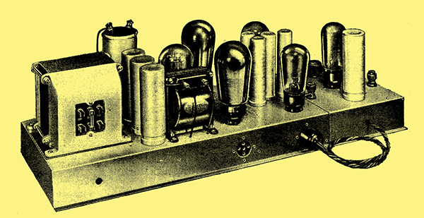
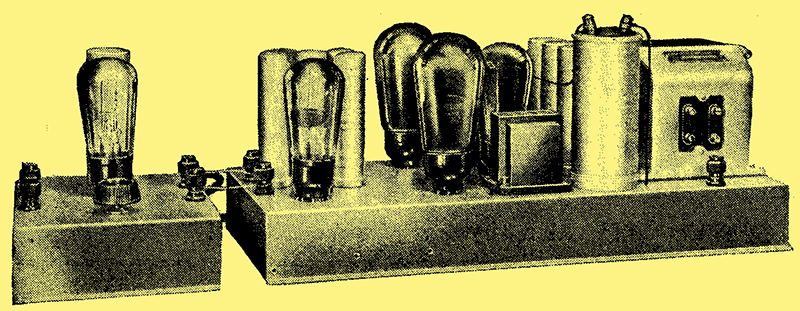
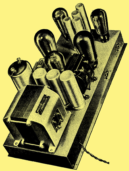
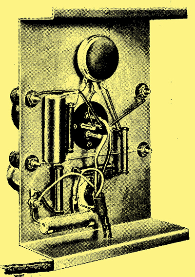
A view of the amplifier and feeder unit. It should be noted that in the final model the mains transformer has been turned round for convenience in wiring.
Unlike the ordinary push-pull system, an amplifier of this type is not balanced as regards disturbances in the HT supply ; thorough decoupling of the anode circuit of the first stage is necessary, therefore, and is provided by the 50,000Ω resistance R19 and the 8 μF capacitor C16. Grid bias is obtained by the voltage drop across the 2,000Ω resistance R21, and as the anode current is about 1.2 rnA., a bias of 2.4 Volts is obtained. A 250,000Ω tapered potentiometer in the grid circuit of the valve provides volume control. It is important to note that neither of the input terminals to which a pick-up is connected is earthed, this being an inevitable consequence of the particular method adopted for feeding the push-pull stage. Care must be taken, therefore, to see that the pick-up leads do not become accidentally earthed, for they are about 60 Volts above earth potential.
The full output is obtained with an input of only 0.265 Volt RMS, so that it is possible to obtain adequate volume from the more insensitive types of pick-up. The range of control afforded by the volume control is adequate, however, even when a component giving a large output is used. On radio, or when both radio and gramophone are required, alternative methods of feeding the amplifier are available, and these will be dealt with next.
The main amplifier.
The considerations underlying the design of the Push-Pull Quality Amplifier have already been dealt with, and here details of the various methods which can be adopted for providing its input, both for radio reception and gramophone reproduction.The choice of suitable associated equipment, including both loud speaker and pick-up, is also considered.
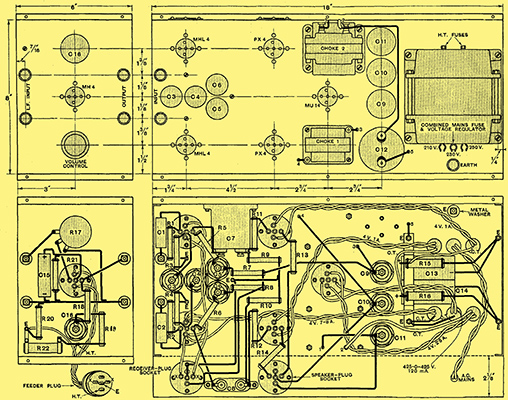
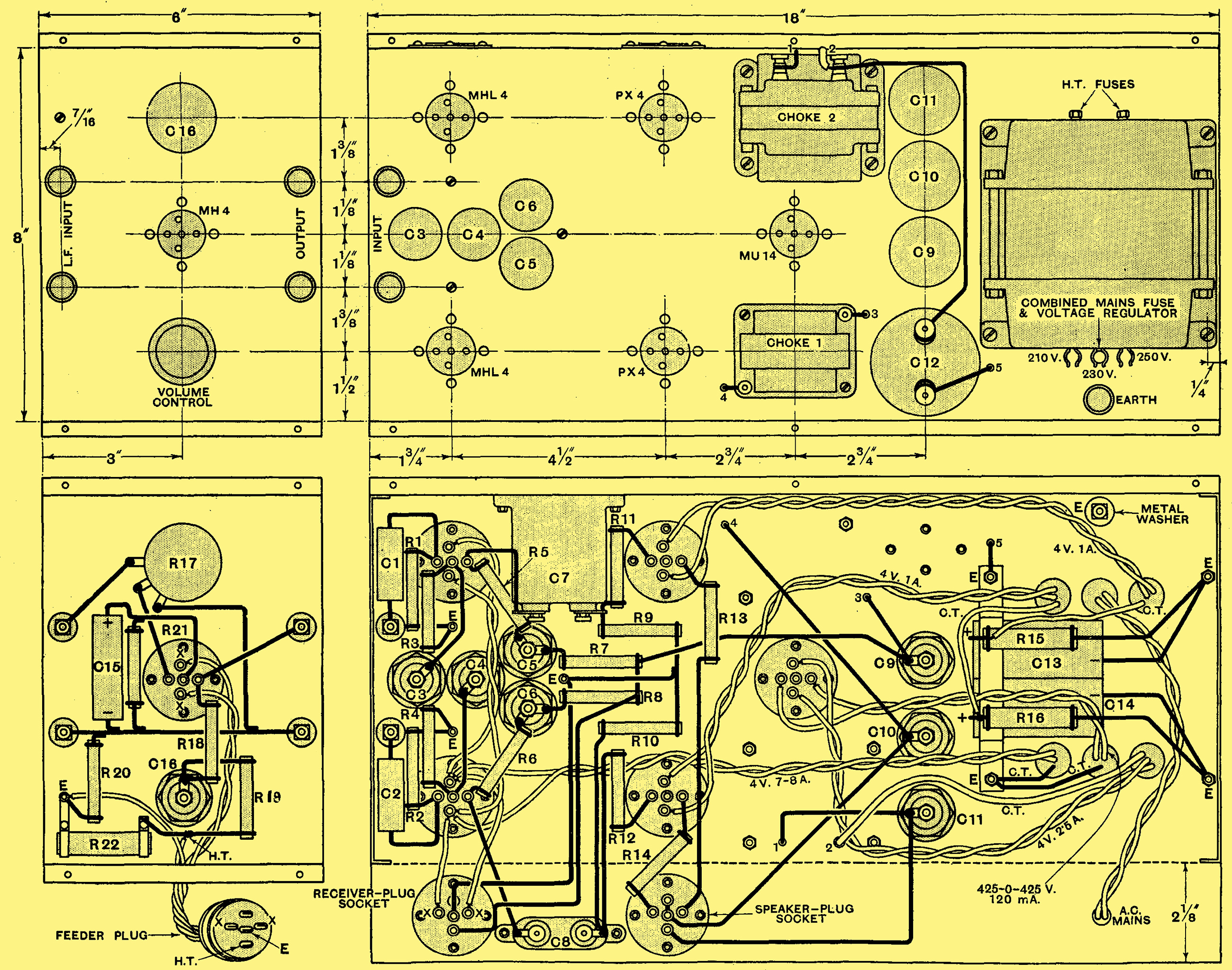
These drawings show the construction and wiring of both the amplifier and the feeder unit. Care should be taken to ensure a good contact between the chassis and the cans of the electrolytic capacitors.
The construction of the Push-Pull Quality Amplifier is so straight-forward that it calls for little in the way, of explanatory comment; it may be mentioned, however, that all the terminals, except the earthing terminal, must be insulated from the chassis by the bushes provided. The connections to the negative terminals of most electrolytic capacitors are made by the contact of the cans with the metal chassis. As the chassis is cellulose finished, care should be taken to scrape off sufficient paint beneath the capacitors for good contact to be obtained.
The mains transformer is fitted with fuses in the HT secondary, rated at 150 mA, and the adjustment for mains voltage is made on the primary by inserting the 1 Amp fuse into the appropriate clips. When the amplifier and feeder units are used alone for gramophone purposes, an earth should be connected to the terminal provided, otherwise hum may be found. If the amplifier be used with a radio set, however, this will not be necessary for an earth will be used on the receiver itself.
Since the amplifier is so inherently free from distortion some care should be exercised in the choice of the associated equipment. The loud speaker, in particular, should receive especial care. Although the best results would probably be secured by the use of a large resonance-free moving-coil speaker, giving an even response up to some 3,000 Hz, in conjunction with a special high-note 'tweeter' for the range above 3,000 Hz, this is hardly a matter of practical politics at the present time. Few small horn speakers for high-note reproduction are available, and the cost of present types is greater than that of large moving-coil models, so this specialised dual combination is of restricted appeal.
Loud Speakers
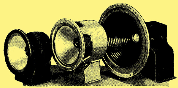
A group of high-quality loud speakers; from left to right they are the Ferranti M.1, the Parmeko, and the BTH RK Senior.
The best results at reasonable cost, therefore, are probably to be obtained with a single speaker of the larger class. In general, the cone should be of fairly large diameter and freely suspended; so much depends upon the details of design, however, that it is difficult to give any definite ruling. A number of speakers have been tested with the Push-Pull Quality Amplifier, and among the energised type the BTH RK Senior has been found very satisfactory. This speaker is normally available with a field resistance of 5,000Ω, but it is understood that the makers can supply it to order with a field resistance of 1,250Ω. The speech-coil impedance is 15Ω, so that the output transformer should have a ratio of 25.8:1.
Although of considerably smaller dimensions, the Ferranti M1 speaker is capable of an exceptionally good performance, and will handle a large input without distress. It is a permanent-magnet model and has a speech coil impedance of 20Ω, so that the output transformer should have a ratio of 22.4:1. The Parmeko speaker is also a permanent-magnet type with a speech-coil impedance of 16Ω, and calls for a transformer ratio of 25:1.
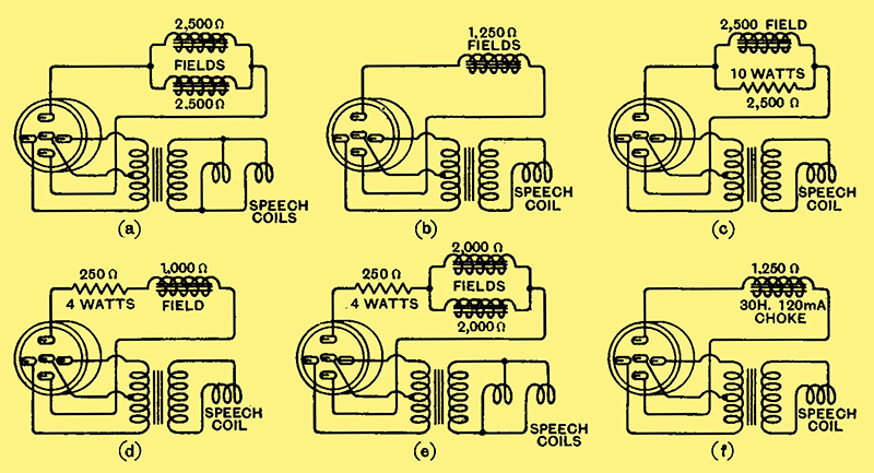
Fig. 4. - The various speaker connections for different cases are illustrated, at (a) for dual speakers with 2,500Ω fields, at (b) for a single 1,250Ω speaker, at (c) for a single 2,500Ω field, at (d) for a single 1,000Ω field, at (e) for dual 2,000Ω speakers, and at (f) for a non-energised speaker.
If an energised model is to be used, it should have a field resistance of 1,250Ω and require a current of 120 mA. Other resistances may be used, however, provided that they are connected correctly, and details of the commonest arrangements are given in Fig. 4. If a permanent-magnet or separately energised speaker be used, it will be necessary to employ a 1,250Ω speaker field replacement type choke to obtain correct smoothing and voltages; a suitable component is obtainable from Sound Sales. The question of loud speakers leads naturally to the transformer which must be used for coupling the speaker to the output stage. For a negligible loss of bass, the transformer primary reactance at the lowest frequency required should not be less than the load impedance of the output stage. If it be made equal, however, the load impedance will be below optimum, even although the frequency response may be unaffected. In order to avoid amplitude distortion at low frequencies, therefore, it is desirable for the primary reactance to be not less than twice the load impedance. If the lowest frequency required be taken as 50 Hz the inductance should be about 63 H for a 10,000Ω load impedance. If 20 Hz were required, the inductance should be 160 H.
For the maintenance of the high-frequency response, however, low leakage inductance is required, and it is difficult to obtain this with a high primary inductance. Some compromise is necessary, therefore, and as frequencies below 50 Hz.occur very rarely in music and speech, it is safe to base the design on this frequency. It is recommended, therefore, that the component, constructional details of which appeared in The Wireless World for September 8, 1933, be used. This has a primary inductance of. 69 H, so that the theoretical conditions are fully met down to 46 Hz, and an even response is maintained to below 23 cycles.
In spite of its high primary inductance the leakage inductance has been kept at a low figure with the result that there is a loss of only 2 dB at 10,000 Hz. The transformer, in fact, is specially designed for use with a push-pull PX4 output stage, and it was used when taking the frequency response curves given last week and also when measuring the input-output characteristics.
The only other point which should be mentioned in connection with the equipment relates to the gramophone pick-up. Any good quality component maybe used but the writer was particularly pleased with the performance of the BTH needle-armature pick-up. Although its output is below the average, it is ample for the Push-Pull Quality Amplifier.
Feeding the Amplifier
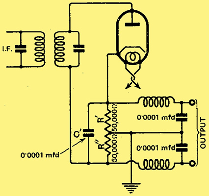
Fig. 5. - The amplifier may be fed directly from the diode second detector of a superheterodyne by adopting the connections shown in this diagram.
Turning now to the question of feeding the amplifier, the feeder unit is necessary only when radio is not required. When it is, other methods must be adopted. When radio only is needed the simplest arrangement is that shown in Fig. 5. It will be seen that a diode detector is used, and the load resistance is split into two equal parts, R' and R'', the centre-point being earthed. The LF potentials developed across the resistance as a whole are then equal and opposite in phase across the two halves. Two HF chokes and by-pass capacitors are needed in the output if HF potentials are to be kept out of the LF circuits. The valve used may be any indirectly heated triode with the grid and anode strapped together. The scheme shown in this illustration is suitable for a superheterodyne where the tuned circuit need not be earthed; for a straight set, however, the alternative arrangement of Fig. 6 is more convenient.
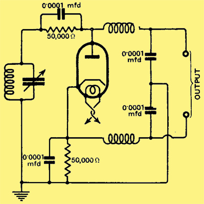
Fig. 6. - An alternative method of feeding the amplifier from a diode detector is available in the case of a straight set.
The amplifier requires an input of 7.1 Volts peak, so that if it is to be fully loaded on an 80% modulated signal the diode input must be about 8.5 Volts RMS. This is a large input, but only just large enough for distortionless rectification. It means, however, that an HF stage will be needed even for local reception. If it be desired to use this method of feeding the amplifier on radio and still retain gramophone reproduction, a duo-diode-triode can be used with switching for changing from radio to gramophone.
It should be noted that with the direct feed from the detector, LF volume control is very difficult to arrange, and in general a pre-detector control must be used. It would seem worth while, therefore, to employ an extra stage of LF amplification on radio, for this will always be needed on gramophone. The circuits of Figs. 5 and 6 seem only justified in cases where gramophone reproduction is not required.
It the extra stage (as in the feeder unit) is employed it is necessary to use a duo-diode-triode with the connections of Fig. 7. It is important to note that the tuned circuit must not be earthed, and that AVC cannot usually be obtained from this valve. It is probable that this will be the arrangement usually employed and it is for this reason that the performance curves of the amplifier were taken with a duo-diode-triode instead of the MH4 type.
One point worthy of mention arises in connection with this arrangement on radio. The detector requires an input of about 10 Volts RMS for truly distortionless rectification with modulation depths up to 80%. As a result, the maximum LF output will be about 9.6 Volts peak. The triode, however, only requires an input of 0.265 Volt, so that most of the detector output must be thrown away in the volume control, and it will be easy to overload the amplifier.
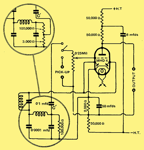
Fig. 7. - Where both radio and gramophone are required the arrangement shown here is one of the most satisfactory. If a large degree of HF amplification be used the connections shown inset are often advisable.
If the HF amplification is insufficient to provide a detector input of 10 Volts, and an HF stage will be necessary even for local reception, there is no alternative to operating the detector at a smaller input. Any distortion which this may introduce does not become serious until the detector input is quite small. Where the full input is available, however, it is best to change the connections of C' of Fig. 7, as above inset, so that with the volume control at maximum the full output of 4 Watts is obtained on an 80% modulated signal with a detector input of 10 Volts. This is the ideal, but not the most economic case, and the extra resistance should have a value of 3,000Ω.
The precise connections adopted for radio use will naturally vary in different cases, depending upon the design of the receiver, The foregoing notes, therefore, are intended chiefly as a guide for those who wish to use the amplifier with an existing set ; it should not be forgotten, of course, that such a receiver must introduce very little distortion if any great improvement in quality is to be found. For television work, of course, the input requirements are the same as those for sound broadcasting. It may be pointed out that it is hoped to describe at a later date the modifications necessary to the Single-Span Receiver for using it with this amplifier, for this receiver is particularly well adapted for high-quality reproduction.
An underbase view of the gramophone feeder unit.
During the tests on the amplifier various speakers were employed, and the quality of reproduction was instantly noticeable as reaching an unusually fine standard. The presence of the highest audible frequencies in the amplifier output was marked by a great increase in the naturalness of the reproduction, and not necessarily by an increase of brilliance. The so-called brilliant reproduction is often due to an accentuation of frequencies around the 4,000-5,000 Hz mark, and is often found with a lack of the extreme upper register. The increase in response to 10,000 Hz gives quite a small change in the quality, but it greatly adds to the naturalness of speech and music.
The freedom from amplitude distortion was most marked during the tests, and the increased purity showed that the distortion introduced by ordinary equipment. although it may not be great, has a decided adverse effect. In conclusion, it may be remarked that the performance of this Push-Pull Quality Amplifier reaches so high a standard that it is unlikely to be surpassed in the future. The frequency response is practically perfect from 20 to 10,000 Hz, and it is unlikely that an appreciably greater range will ever be needed for sound reproduction. The amplitude distortion is negligibly small up to the rated output of 4 Watts.
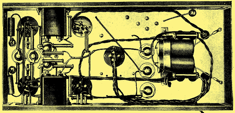
An underbase view of the amplifier showing the wiring. The two electrolytic bias-resistance by pass capacitors for the output stage can be seen on the right supported bv a strap.
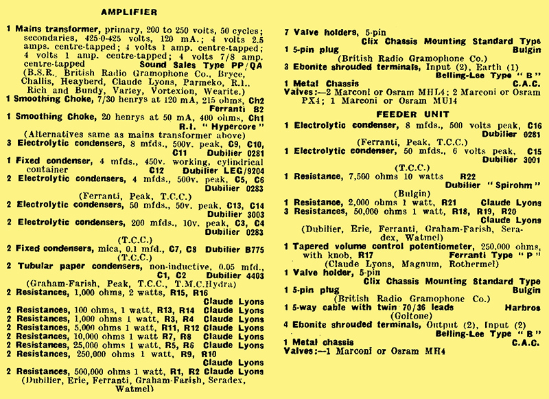
List of Parts
After the particular make of component used in the original model, suitable alternative products are given in some instances.
|