|
A Microprocessor Controlled Valve Tester

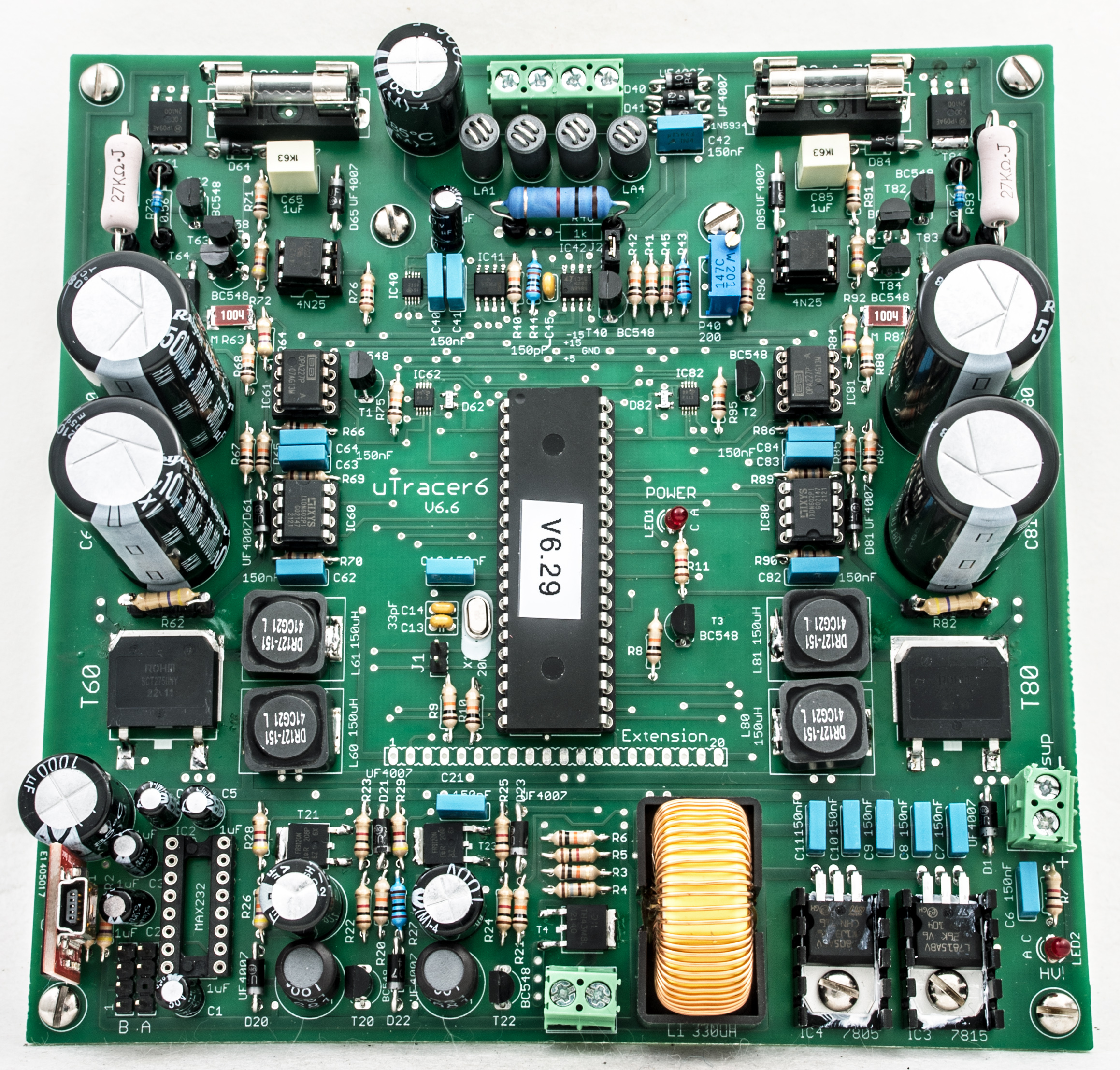
G8LSD's completed μTracer 6 board. Click for large image.
The μTracer (search for utracer on Google) is a single board microprocessor controlled valve characteristic measuring tool. The μTracer has been designed by Ronald Dekker and kits are available from his website.
The author built the μTracer 3 back in 2018 and it has proved to be an excellent instrument. The drawback of the μTracer 3 was the heater supply. The author found that in practice it was better to use an external power supply for the heater - taking care not to make mistakes in heater settings.
The μTracer 6 was an excuse to embark on another project and to try different ideas in the mounting of the valve-holders etc.
Unlike the μTracer 3 the calibration phase takes place after all the main sections have been constructed and tested to a basic level of output.
Old-School Surface Mount Technique
Back in the early '90s when first building 10 GHz modules with small surface mount components and before the widespread availability of solder paste etc. it was suggested that a vertically mounted knitting needle would keep the device in place long enough to tack solder one side. A modern 'third hand' can provide such a frame.
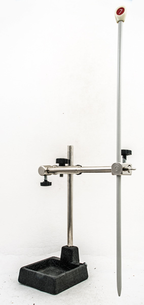 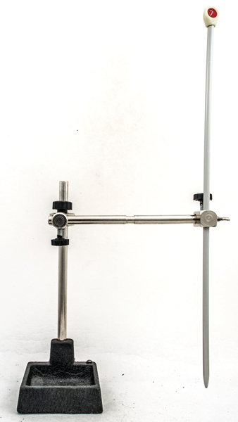
Using a knitting needle as a surface mount component holder.
Another method that was used and worked well for power transistors as well as resistors used a Multi-Mini Vice that was advertised in Radio Constructor back in the 1960s. This has a heavy base and the arrangement shown below worked particularly well. It was found that the transistors benefited from having the contacts cleaned with a fibreglass pen prior to soldering - less work for the flux to do. For all joints 22 SWG Savbit Solder was used. The author does not have solder paste and liquid flux.
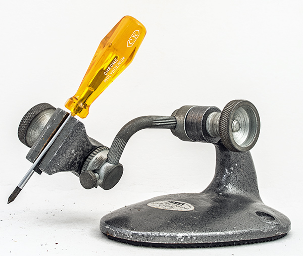
The Multi-Mini Vice as a surface mount component holder.
Construction
The construction manual is fully detailed and the construction progresses stage by stage with testing of each module as built. Basic build techniques were written-up for the μTracer 3.
Some of the smaller surface mount components are pre-mounted onto the board when received. Other surface mount components are mounted as the construction progresses.
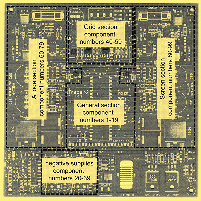
Guide to the location of each module.
Building commences with the COM port and Graphical User Interface installation (GUI) The μTracer 3 GUI is required as some software is used for the GUI for the μTracer 6. The USB - COM port runs at 9600 Baud.
To be inclusive the μTracer takes RS232 and converts to TTL using a MAX232N chip. The socket for this chip is on the bottom left of the board. The USB input module used by the author converts to TTL and the μTracer 6 has a header fitted that matched the FTDI standard and so the module plugs directly onto the header leaving a micro USB socket on top for connection to the PC.
After testing the GUI to TTL process the regulators are then added and tested. This section can be seen in the lower right of the main image. The regulators provide 15 Volts and 5 Volts from the 19.5 Volt input from a laptop brick type of power supply.
The RS232 interface was built and tested and then the MAX232N was removed as not needed for this instrument.
The microcontroller at the heart of the instrument is a 16F884 PIC in a 40 pin format that is clocked at 20 MHz. Building the module was straightforward but testing generated an undocumented error and hours of head scratching. The 40-pin PIC was pressed firmly home in the socket and the circuit was checked before applying power from a current limited supply. Sleeping on the problem suggested a possible faulty PIC. With the suggestion to check that the PIC was fully inserted into the socket the author used both thumbs on the PIC and used considerable force to prove that previous technique was sound. However, at the third application of ever increasing force, the PIC moved about 0.5 mm further into the socket. Re-testing immediately produced the correct response from the board. Lack of familiarity with 40 pin IC's can be seen as the author's problem.
Between the RS232 interface and the main voltage regulators is the heater supply and this is built and tested next. The large inductor is required as considerable continuous energy is required from this circuit. 6.3 Volt at 1.5 Amp was the test and nothing became warm except the valve used as the load.
Negative voltages are required for grid bias and this circuit sits to the left of the heater supply and against the RS232 module. Initial testing gives -80 Volts .
Having built the negative voltage generator, the next module assembled is the grid bias control. This is situated top centre of the board. Testing this employs the PC and GUI. Again the voltages are checked to be roughly correct and fine tuning comes with calibration.
Every section has a checklist against every step of assembly with reference to hints and tips where appropriate - this is most comprehensive. The big builds are the high voltage generators. These sit either side of the microcontroller and have 56 steps to complete. Building for pleasure affords the luxury of working slowly. In working with each component individually there are fewer opportunities for making errors. Testing the HT generators is via the GUI with meters connected to both outputs at once (if two DVM's are available). Much caution is needed for these tests as the HT is contained within two 500 Volt electrolytic capacitors connected in series and a lethal amount of energy is present until the capacitors are discharged. The voltage is shared between the capacitors and safely discharged by two surface mounted resistors placed on the rear of the board and in parallel with each capacitor.
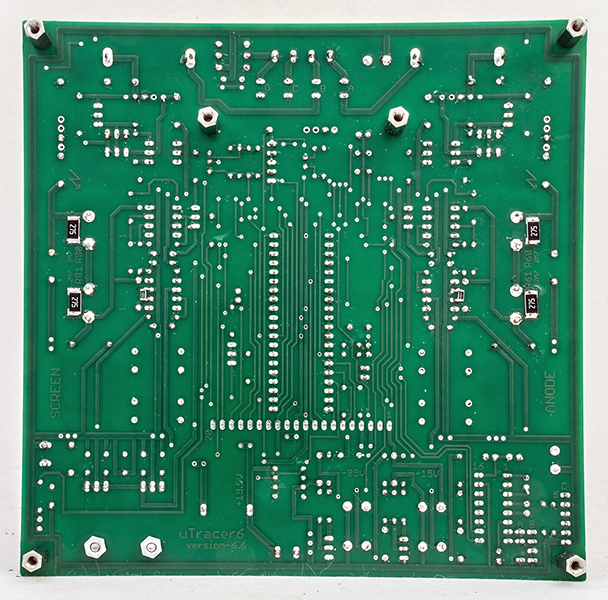
The rear of the board with surface mount resistors.
Two 10kΩ resistors are also mounted on the reverse of the board between pins of IC60 and IC80. Wire ended resistors are supplied but the author had a supply of 1206 surface mount resistors that are the correct size to fit between the pins.
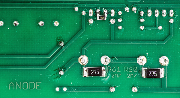
The author's surface mounted resistors on the rear of the board.
The final sections to complete the build are seen at the top of the board above the HT generators. These are the high voltage switches.
Calibration
To be continued.
|