|
This tiny instrument has been made possible by the omission of some of the circuits normally associated with oscilloscopes, together with the use of an extremely simple timebase. The design is primarily intended for the more experienced constructor who is capable of devising his own wiring layout. By dint of winding the mains transformer and using mu-metal screening, the author built the prototype within a case measuring 3 in × 4 in × 5in; but, even without these two aids to miniaturisation, units built up to the circuit need only be marginally larger in size.
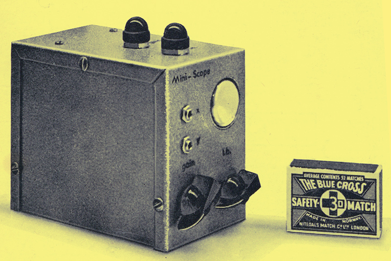
The Miniature Oscilloscope.
This small scope was built to enable traces to be examined in the alignment and repair of radios and amplifiers. Some people prefer to work with an oscilloscope as it shows distortion and its causes more readily than is possible when judging by ear. This oscilloscope is, as can be seen from the diagrams, within the 'scope' of most people who have had some experience in the field of electronics.
Although the tube is only 1 inch in diameter, this is sufficient for most purposes.
The Y amplifier is capable of a response from 5 Hz to 150 kHz ± 3dB, the useful response including 465 kHz. 2 V peak-to-peak input at 0 dB attenuation fills the screen from top to bottom. The timebase generator provides sweeps from 30 Hz to 150 Hz. There is also an X input for examination of Lissajous figures.
The prototype measures only 3 in by 4 in by 5 in, and is easily carried around and used for on-site repairs. It was decided to simplify the normal circuitry considerably, doing away with sync, brightness, focusing and astigmatism controls. There are two preset controls, one for X gain and the other for trace linearity.
It was at first planned to transistorise the unit. However, as the tube heater took 0.3 Amp and some form of EHT supply would be required, this would make a heavy drain on a battery. If, therefore, a mains supply was to be used, why not employ valves? There seemed little point in using transistors just to transistorise the design.
The Circuit
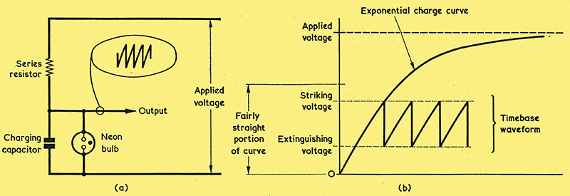
Fig. 1( a ). The basic neon relaxation oscillator. (b). Illustrating the relationship between applied voltage and linearity of the sawtooth waveform produced by the neon oscillator.
Since audio frequencies only were to be examined, it was decided to use a neon relaxation oscillator for the timebase. Although the Miller sawtooth generator is best for this application, to use it to its full benefit one would really need a larger tube.
A neon relaxation oscillator is very simple to build and, with careful selection of the neon, can provide a very linear sawtooth waveform. The operation of the neon relaxation oscillator has been covered often. enough in the technical press and in text books, and; the basic circuit employed is shown in Fig. 1(a).
From Fig. 1 (b) it can be seen that the higher the voltage applied to the series resistor, the lower is the portion of the exponential curve which is used. Unfortunately, if the applied voltage is too high the neon will strike and remain illuminated, with the glow probably appearing at one end of the electrodes and having a purplish tinge instead of the orange tint normally associated with a neon bulb. Some neons are better than others in this respect. The neon used in the prototype was one of the wire-ended indicating type (Home Radio Cat. No. PL32A) and was selected from five bulbs of the same type for best practical results in the circuit.
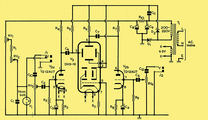
Fig. 2. The circuit of the miniature oscilloscope.
In the full circuit diagram of Fig. 2 the neon relaxation oscillator circuit is given by RV1, R1, RV2, C1 and V1. Here, RV1 is the linearity control and it functions as a potential divider applying a preset voltage to R1 and RV2. The latter is the horizontal frequency control. RV1 is set so that, at the highest frequency selected by RV2 (where it inserts minimum resistance into circuit) the neon is just below the 'splash' point just mentioned. In the prototype, the slider of RV1 was set nearly at the HT positive end of its track.
The timebase signal is taken via the X input jack socket to the X gain control, RV3, and thence to one half of a double triode, V2(a). This is the X amplifier. Upon inserting a jack plug into the X input socket, J1, the timebase signal is cut-off and an external X signal can be injected.
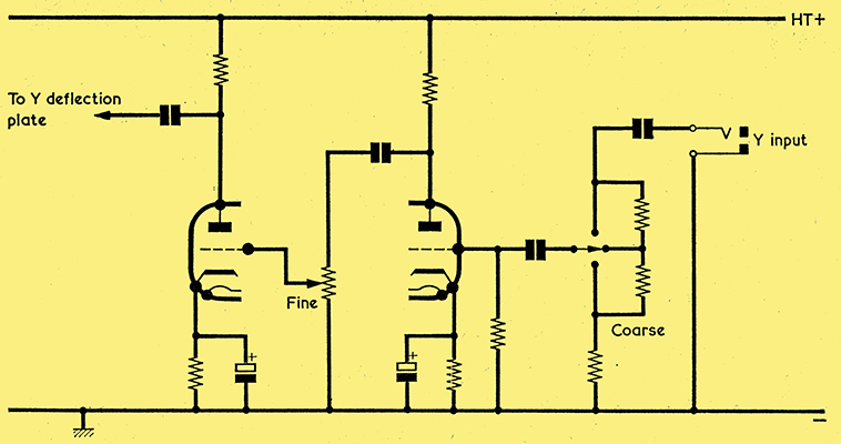
Fig. 3. Basic circuit for an alternative Y amplifier.
The double triode could have been used as a 2 stage Y amplifier only, as shown in basic form in Fig. 3. This would have increased the Y sensitivity considerably, but would have meant that the neon was driving the tube direct, and as there is only about 30 V between striking and extinguishing voltages this is not really sufficient for a full sweep. Nevertheless, the idea is suggested for those who wish to experiment.
By using the double triode for both X and Y amplifiers, relatively low signals can be fed into the X socket. Both amplifiers are identical. To obtain a good low frequency response C6 and C7 should have a high value, as specified.
The valve used is a 12AU7. This is a medium gain valve. The range of double triodes provided by the 12AT7, 12AU7 and 12AX7 is a very useful one and can offer a lot of advantages, particularly as all three valves have the same pin connections, making them interchangeable. With the 2 prototype, the 12AU7 gave highest frequency coverage. [★] The rather high value specified for V2(b) cathode bias resistor, R8, is that employed in the prototype and was found to be optimum for gain and linearity. However, it means that the valve runs at a very low anode current and it may be found that R8 may have to be reduced in value by quite a considerable amount with some 12AU7's. R3 may be similarly reduced in value if it is found that an improvement in X gain and linearity results. - Editor.
The tube itself, a DH3-91, is ideal for this type of project owing to its small size, being only about 4 in long. Asymmetrical deflection was used, and as the brightness was about right for normal viewing and no focusing was necessary (the tube is a self-focusing type) no EHT potential chain was needed. No centralising control is required, the spot being comfortably central provided that C6 and C7 have very low leakage. The pin connections to the tube shown in Fig. 2 cause the usual X and Y plate functions to be transposed. (In normal usage, the X plates are pins 4 and 6, and the Y plates are pins 2 and 3.). [★] The true X plates of the DH3-91 are intended for symmetrical deflection and the true Y plates for asymmetrical deflection. Because of this difference, and since the electrode connections employed in Fig. 2 give the required centring in practice, these connections should be employed (although the use of the X and Y plates for their intended function could, of course, be checked out experimentally if desired). The DH3-91 is a current Mullard CRT and may be purchased through radio retailers in the normal manner. - Editor.
Power Supply
The mains transformer should have an HT secondary offering about 200 to 220 V, together with a 6.3 V heater winding. D1 acts as a half-wave rectifier and supplies HT voltage for the two triodes and the neon oscillator. In company with D2 it also appears in a voltage doubling, circuit allowing a doubled EHT voltage to be available for the final anode and deflector plates.
Not having access to a mains transformer of suitable size, the writer decided to try hand-winding one. This really isn't as bad as people make out! By taking care he had only one break in the secondary, which used 50 SWG wire.
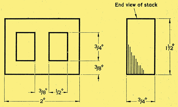
Fig. 4. Dimensions of the laminations used for the home-wound mains transformer. The stack size is ¾ in.
The core employed was salvaged from a heater transformer in an old radio, and the lamination dimensions are given in Fig. 4. The central core size was ⅜ in by ¾ in, and the laminations were interleaved (i.e. the core was made up of alternate E's and I's. The transformer was wound in the following manner.
Primary: 2,880 turns of 40 SWG enamelled copper wire.
Secondaries: 2,400 turns of 50 SWG enamelled copper wire, and 85 turns of 26 SWG. enamelled wire.
These secondaries give an output of 210 V AC and 6.3 V AC respectively.
For those who do not wish to wind the transformer some very small ready-made components are suitable, although they may not be quite as small as that made up by the writer. [★] A particularly suitable transformer here would be the Osmabet component available from Home Radio under Cat. No. TM26. This has secondaries of 200 V at 25 mA and 6.3 V at 1 A, and its dimensions are 1⅞ in by 2⅛ in by 2 in, with 2½ in fixing centres. - Editor. The power required by the oscilloscope circuits is very low. Heater current is 0.6 A and HT current is only of the order of a milliamp.
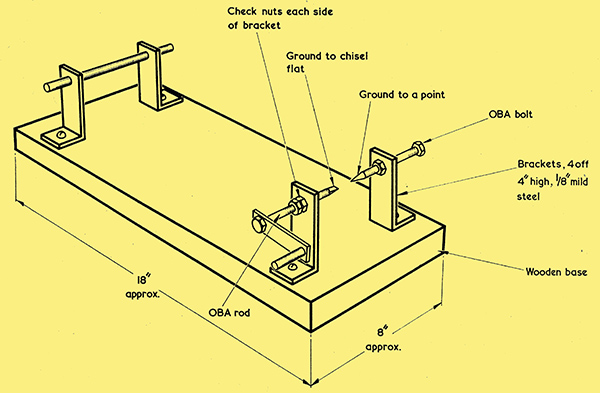
Fig. 5. A simple hand winder for winding coils and transformers.
If the constructor plans to wind the transformer himself it is a good idea to use a winder of some type. This can be anything from a hand drill held in a vice to a professional motor driven winder. It is fairly easy to make an adequate winder from bits of scrap wood, etc., and Fig. 5 shows a typical example. The writerbs winder was fitted with a GPO electro-magnetic counter driven by a switch on the handle. A handy source of interleaving paper can be found in non-metallised paper capacitors.
Construction
The dimensions of the case in which the complete oscilloscope is housed depend to some extent upon the size of the mains transformer. The prototype, using the authorbs home-wound transformer, was housed in an Imhof Minibox measuring 3 in by 4 in by 5 in. [★] The Minibox referred to is type M3030 and is available by mail order from Alfred Imhof Limited, Ashley Works, Cowley Mill Road, Uxbridge, Middlesex. It should be mentioned that orders for Miniboxes and other Imhof instrument cases and housings under £5 are subject to 25% surcharge, and carriage and packing is extra. - Editor. Suitable alternative cases may be made up following normal metal-working techniques.
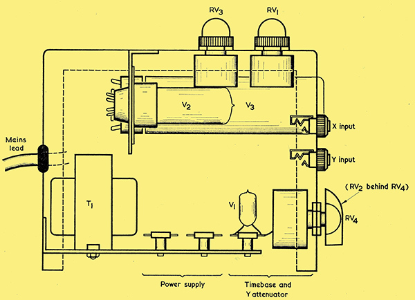
Fig. 6. The layout of the principal components inside the case.
As can be seen from Fig. 6, V2 and V3 are mounted on a small bracket and hang from the top of the box. Most of the components associated with the valve and the CRT are mounted directly on to the valve and CRT bases.
The ideal position for the mains transformer would have been with the laminations in line with the tube; however, in the position shown there is very little magnetic hum pick-up, and this can be cured by screening the transformer with small pieces of mu-metal. A word of warning is required here. Don't bend mu-metal more than can be avoided or it loses its marvellous screening properties. [★] Mu-metal has been available in the form of govt. surplus CRT-shields and the like, but it may be a little difficult to obtain these days by readers who rely on general mail-order suppliers for components. If no mu-metal can be obtained it would be better to design the case so that the mains transformer can be mounted with its laminations in line with the CRT - Editor.
The lower part of the case is used for the power supply and timebase circuits. Several small tag-strips are adequate for mounting the components concerned.
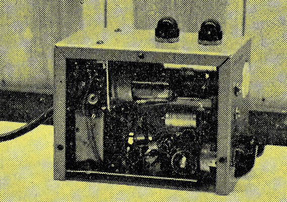
Side view, showing the internal components of the oscilloscope.
In the side view of Fig. 6, RV4 is mounted on the front panel, with RV2 behind. RV1 and RV3 are panel-mounting preset potentiometers with plastic covers fitted over their spindles. (These covers were non-standard items found in the writer's spares box and are not, of course, essential.) A saving in space could be given if miniature skeleton preset potentiometers were employed instead, these being positioned inside the case with access when the case side is removed.
A 3-core mains lead passes through a grommet at the rear of the case and allows for connection to the mains via a 3-way plug. The mains lead ensures also that the metal case of the oscilloscope, which is common to the chassis line in Fig. 2, connects reliably to the mains earth. There is no on-off switch in the oscilloscope itself, this function being carried out by the switch at the mains socket to which it is connected.
Attenuator Probe
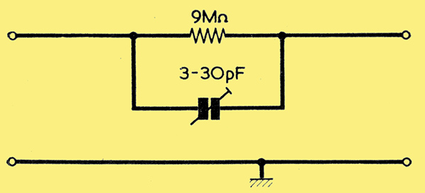
Fig. 7. A simple divide by 10 probe, which can be used externally.
A divide by 10 attenuator probe can be very useful in some instances and it consists of a 9 MΩ resistor bypassed by a 3-30 pF trimmer, as shown in Fig. 7. The trimmer is set so that, when a square wave is fed in, there is no overshoot on the leading edges (i.e. there is a flat frequency response).
Conclusion
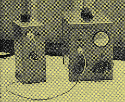
The oscilloscope coupled to a home-built audio oscillator.
In conclusion, the writer would like to state that the prototype has given no trouble and, at the time of writing, has had about 200 hours running as a monitor coupled to a stereo amplifier in addition to a demonstration at the Shefford Radio Club and other usage. Also, despite the small size of the mains transformer and the winding details (2,500 A per sq in), the unit runs very cool.
| 