|
Ultra Short-wave Frequency-Changers.
The choice of a frequency-changer which is suitable for operating on the extremely high frequencies involved in high-definition television is by no means easy, for most types exhibit serious defects. These defects are discussed in this article, and they are shown to be due chiefly to stray capacity couplings, the effects of which can be eliminated by the use of a new circuit embodying two valves.
The present experimental, and the future regular, television transmissions of high definition are carried out on wavelengths of some 5 to 9 metres, because longer wavelengths are unsuitable. In the case of sound broadcasting, even the highest standard of quality does not demand the reproduction of a wider range of frequencies than about 30 Hz to 15,000 Hz. High-definition television, however, demands a range of frequencies of at least 25 Hz to 1,000,000 Hz! The lowest frequency required depends upon the number of pictures a second, the highest upon the maximum rate of change of light. The latter is consequently a variable quantity depending on the type of picture, but the figures just given can be taken as approximately right when there are twenty-five pictures a second and 240 scanning lines.
Now it is well known that the carrier frequency must be higher than the highest modulation frequency, so that it would be quite impossible to transmit high-definition television from any station working on a wavelength, greater than 300 metres (1,000 kHz). Even if such a wavelength were chosen, the sideband spread would extend from zero frequency to 2,000 kHz it would occupy the whole range of wavelengths above 150 metres. It would cause interference with every station within this range, and, conversely, reception would be marred by any transmission on a longer wavelength than 150 metres!
Ultra-Short Wavelengths
It can thus readily be seen that transmission on the normal broadcasting bands is out of the question. It is possible on the ordinary short wavelengths,of-course, but there are two reasons why it is not very practicable, In the first place, these bands are now crowded with broadcasting and commercial transmissions, and, secondly, selective fading is of common occurrence; the effect of this is serious enough on telephony, but it would be much worse in television.
The ultra-short Wavelengths are thus the only ones on which high-definition television can be carried out, and the band used for this purpose will probably be 5 to 9 metres, the first transmitter having a wavelength of some 7.5 metres. This does not seem a very wide band, but it is really enormous, for 5 metres corresponds to a frequency of 60 MHz and 9 metres to 33.3 MHz. The band width is thus 26.6 MHz, and even with the large spread of. television transmitters, there is room in it for some thirteen stations. A better idea of the enormous width of the band can be gained when it is realised that if it were used for telephony transmissions with the usual station spacing of 9 kHz, nearly 3,000 stations could be accommodated.
The ultra-short wavelengths differ from longer wavelengths in many ways, and as far as present knowledge goes they are of a quasi-optical nature. They do not appear to be reflected by the Heaviside layer, with the result that, although fading is absent, long-distance reception is impossible. In general, reception is confined to within a distance perhaps 50% greater than the optical. It is as yet, however, too early to say what are the limits of reception, and it seems possible that the limiting distance is greater than is often thought.
The properties of these wavelengths, therefore, are rather a matter of speculation at the present time, for although there is a great deal of data on their behaviour, it is by no means complete. It is, consequently more profitable to turn our attention to receivers, and it will be found that sets for television reception must differ from ordinary broadcast sets in many features because of two fundamental differences - the very high signal frequency and the very wide band of frequencies which must be passed.
In order to clarify our ideas, let us consider the reception of a station on 7.5 metres. The frequency is 40 MHz, and, allowing for modulation frequencies up to 1,000,000 Hz, its total spread is 39-41 MHz. For distortionless reproduction of the picture, all frequencies in this band must be received and amplified faithfully. The super-regenerative receiver seems unlikely to be of much service on account of the high level of background noise which it introduces and also because of its tendency to distortion, so that the choice of a receiver falls upon the straight set and the superheterodyne. Experience with ordinary short-wave receivers shows it to be difficult to obtain a stage gain of more than 1 or 2 times at 15 to 20 metres, and unless care be taken the valve may even act as an attenuator. If it be difficult to obtain HF amplification at these wavelengths, how much more so will it be at 7.5 metres, Although it cannot be said that the straight set is an impossibility, the superheterodyne is much simpler at the present time. Such a receiver can be divided into four distinct parts, all of which differ from their counterparts in a medium wave broadcast set. There is first the frequency-changer, secondly the IF amplifier, thirdly the detector, and fourthly the LF amplifier. The IF amplifier must have a band width of 2 MHz and provide adequate amplification; the frequency used can be anywhere from about 3 MHz to 12 MHz, and 4 MHz is a convenient figure, The LF amplifier must give a minimum of amplitude distortion with an output of some 20 Volts, While possessing a flat overall frequency characteristic from 25 to 1 MHz. The detector requirements are even more difficult to meet, for this piece of apparatus must operate with an input of some 4 MHz and give an output over practically the whole range of frequencies up to 1 MHz.
The Frequency-Changer
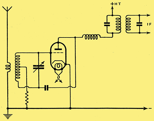
Fig. 1. - The fundamental connections of an autodyne frequency - changer. A screen-grid or HF pentode valve can also be used.
It is, however, primarily with the frequency-changer that we are concerned in this article, and let us clarify the problem by assuming that we are to receive a station on 40 MHz, and that the intermediate frequency is 4 MHz. The oscillator, therefore, must function on either 36or 44 MHz. The simplest form of frequency changer is undoubtedly the autodyne, the fundamental circuit of which appears in Fig. 1; the valve used may, of course, be a triode as shown, or a tetrode or pentode. In spite of its simplicity, this arrangement is unsatisfactory for many reasons. In the first place, the input circuit must be mis-tuned from the signal by some 10%, so that there is a decided loss of signal strength. Secondly, the autodyne is not usually an efficient frequency-changer, for it is not easy to control the amplitude of the self-generated local oscillations, with the result that the valve often works in an overloaded condition. Thirdly, and most important, the autodyne is a very good transmitter. With a system such as that of Fig. 1, intense radiation takes place, and were it to become widely used for television reception it is unlikely that there is any district in which interference-free reception would be possible. This point alone should rule out the autodyne frequency changer.
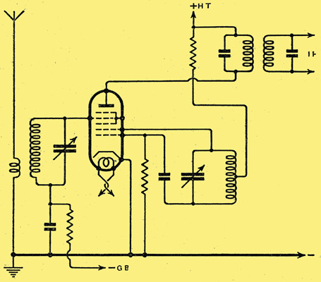
Fig. 2. - The heptode may be employed on ultra-short wavelengths and the Hartley oscillator circuit is most suitable.
The heptode seems the obvious choice for the frequency changer, therefore, since one of the greatest advantages claimed for it is the isolation of the signal and oscillator frequency circuits., The arrangement is shown in Fig; 2, and it will be noted that the Hartley circuit is used for the oscillator. since it oscillates, more readily than the usual system of a tuned circuit with reaction, coil. Practical experience shows two difficulties associated with this frequency-changer. The mutual conductance of the triode section of the heptode is fairly low, with the result that difficulty is often experienced in making the valve oscillate at frequencies of the order of 40 MHz. Even when oscillation can be secured, however, it is found that serious interaction occurs between the signal and oscillator circuits. No screening is perfect, with the result that there are small capacities existing between the various electrodes, so that the true circuit diagram becomes like that of Fig; 3.
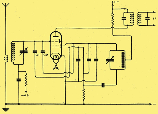
Fig. 3. - The circuit of Fig. 2 is shown here redrawn to include the inevitable valve capacities which are largely responsible for interaction between the tuned circuits.
The capacities appearing across the oscillator circuit do little harm, but it can readily be seen that C1 between the control and oscillator grids couples the two tuned circuits together. Its effect is offset to some extent by C2 between the oscillator anode and the control grid; in fact, if this capacity were given a suitable valve neutralisation of the coupling would result. The coupling upsets the performance of the frequency changer in several ways, it means that oscillator frequency voltages are applied to the control grid, so that the mixing is not entirely electronic; it leads to interaction between the tuning of the two variable capacitors so that an adjustment to one necessitates an alteration in the setting of the other, while the oscillator may cease to function altogether at certain settings of the controls; and radiation from the aerial may occur, although it is unlikely to be as severe as with the autodyne. The coupling is not wholly due to the inter-electrode valve capacities, for there is a negative mutual conductance between the control grid and the oscillator anode which alone can give rise to serious difficulty.
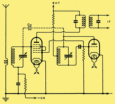
Fig. 4. - Pulling can be reduced by using a separate oscillator to feed the heptode, but interaction is not completely avoided unless neutralising be adopted.
Two of the faults of the heptode can readily be overcome by using a separate oscillator, as in Fig. 4. No use is then made of the oscillator anode, so that the negative mutual conductance effect ceases to exist and no difficulty is experienced in maintaining oscillation because of the higher mutual conductance of separate triode valves. The capacity coupling in the valve, however, is still prominent. This could undoubtedly be neutralised by means of a capacitor, shown dotted at Cn, connected between the control grid and the oscillator anode. It would, however, be difficult to secure a suitable capacitor, for its capacity would be of the order of 0.2 pF only. Moreover, its adjustment would not be easy.
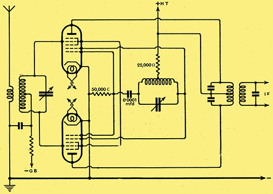
Fig. 5. - A circuit which is inherently free from interaction effects provided that proper screening be used is shown here. Two heptodes are used in push-pull.
An alternative arrangement has been developed, therefore, which is inherently self-neutralised. This is shown in Fig. 5, and it will be seen to consist of two heptodes in push-pull as tar as the input and output circuits are concerned, but in parallel for the oscillator sections. These oscillator sections may be considered as a single triode having a mutual conductance twice that of one section alone, so that no difficulty is experienced in obtaining satisfactory and reliable oscillation over the whole tuning range. A driver valve for the oscillator becomes unnecessary.
Now, in each valve there is a certain coupling to the control grid due to the inter-electrode capacities and the negative mutual conductance effect already mentioned. With identical valves the degree and type of coupling is the same in each case; consequently each control grid is coupled to the same point through an identical type of coupling. In the absence of any dissimilarity in the external grid circuits, therefore, each control grid has impressed upon it oscillator frequency potentials which are identical not only in their magnitude but in their phase. If the tuned circuit be connected between the two grids and its centre point earthed, the two ends of the circuit will always be at the same potentials relative to earth, and the potentials will be in the same phase. In consequence, they can drive no current through the coil and its tuning is entirely independent of that of the oscillator circuit.
The tuned circuit is coupled to the aerial, and signal frequency currents flow in it which set up potentials across its two halves, which are of equal value but of opposite phase. These do not affect the oscillator circuit for the couplings in the valves are to the same point. Mixing takes place in each valve by electronic action, and the intermediate-frequency currents appearing in each anode circuit are combined in the push-pull IF transformer.
In this way it is possible to devise a frequency changer which will, in theory, allow the tuning of the signal and oscillator circuits to be completely independent and yet give efficient mixing, which will allow ready oscillation over the desired tuning range and yet give no radiation from the aerial. In practice, the achievement of these theoretical expectations depends on many different factors. Obviously, the two valves must be alike, but no difficulty has been experienced in the experimental work when using valves of the same make, but otherwise picked at random. The second point of importance is that external couplings must be reduced as nearly as possible to zero. It is obvious that there is no point whatever in choosing a circuit especially for low coupling between the different circuits if stray couplings are to be allowed to outweigh all its advantages. Very thorough screening of the oscillator circuit is essential, and it is usually necessary to screen the signal frequency tuning equipment also. Comprehensive decoupling is required and stray capacity couplings must be guarded against like the plague. A stray capacity of 1 pF does not sound very large, and at 750 metres on the medium waveband it represents a reactance of 4o,000 Ω so that except in certain cases it may not cause much harm. At 7.5 metres, however, its reactance is only 4,000 Ω, and there are few places where it will not exercise a serious effect.
Practical Notes
The push-pull frequency changer is by no means a new idea for it is standard practice in commercial stations. Two triodes are normally employed with the signal applied in push-pull to the grids to which a separate oscillator is coupled in parallel. The IF output is taken from the anode circuits in push-pull. The system is employed because of the absence of interaction between the signal and oscillator frequency circuits, but more because it largely eliminates many of the unwanted modulation products found with most ordinary frequency changers and which give rise to the whistles so common in certain types of superheterodyne. In view of this, it is not improbable that the push-pull system described in this article will find wide application, not only in ultra-short and short wave reception, but also in receivers designed for the medium and long wavebands.
Before concluding, a few practical notes on the circuit of Fig. 5 may be of interest to experimenters. The signal-frequency coil must be centre-tapped and a cylindrical coil on a ⅜ in. diameter former is suitable. About 14 turns of No. 16 gauge wire wound 8 turns per inch is suitable when the capacitor has a maximum capacity of 15 pF. A similar coil but with only 12 turns can be used for the oscillator with the same size capacitor, but here the tapping can be between the centre and about one-quarter the way from the grid. The best point should be found experimentally. Screening and decoupling. must be very thorough. Two points about the valves are important : the screen voltage must be low if stable operation is to be secured; about 45-60 Volts is right, and the valves must not be metallised. The valves are best screened, and if they be separately screened it is probably unimportant whether they are metallised or not, If they are not very thoroughly screened, however, it is imperative that they be un-metallised. Apparently the metallising is not a very good conductor, and instead of acting as a screen in the manner intended it functions as a very effective radiator.
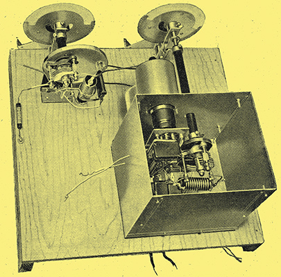
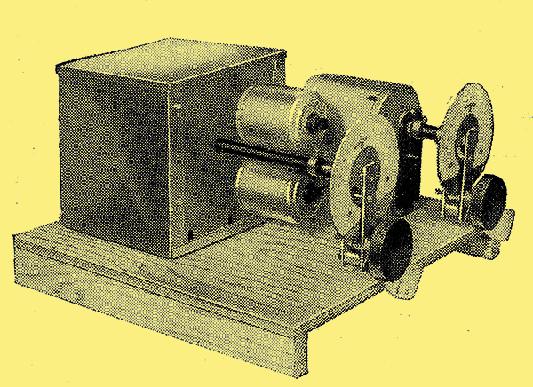
This illustration shows an experimental model of the push-pull frequency-changer. The oscillator components are fitted in the large screening box, and the tuned aerial circuit is contained in a smaller can, the cover of which has also been removed.
|