|

The best of the short-wave broadcasting stations come in on the waveband14 to 50 metres. The short-wave converter here described covers this range and it can be coupled up easily to any good selective broadcast receiver. A remarkably good performance is given by this unit, which incorporates a number of interesting features.
By the addition of a special frequency changer unit, any modern broadcast set can be converted into an efficient and very satisfactory short-wave receiver. The only proviso that need be made is that the receiver includes at least one HF stage if it is of the straight variety, but in the case of super-heterodynes there is no need for an HF amplifier to precede the frequency changer. With a set of this type a double change of frequency is entailed, first from the short waves to the frequency at which the input circuits are adjusted, and then from this frequency to that of the incorporated IF amplifier. It might be thought that the use of two local oscillators would lead to the production of beats, since both will be fairly rich in harmonics, but in practice this does not appear to be troublesome.
Circuit Interaction
Converters employing an autodyne frequency changer, that is to say a single valve serving the dual function of oscillator and first detector, and sometimes preceded by an aperiodic HF stage, have been used extensively in the past in view of their simplicity, but they possess so many disadvantages that the possible alternative schemes, whilst admittedly somewhat more involved, are well worth serious consideration.
When a departure is made from the autodyne arrangement, and a tuned aerial circuit introduced, we are faced with the difficulty of adequately isolating the signal and oscillator circuits. A high intermediate frequency offers a possible solution, but this course is not practical where double frequency changing is employed, since the second oscillator is approaching dangerously close frequency to the first, or short-wave oscillator, and beating between the harmonics of the one and the fundamental, as well as its harmonics, of the other, is likely to prove troublesome. This course is practicable only in a set designed from the commencement for short-wave reception and cannot be applied conveniently to a converter.
A heptode~type frequency changer exhibits this phenomenon on the short Waves, though at broadcast frequencies it is quite satisfactory. One reason is that the signal and oscillator frequencies are so very much higher that the incidental capacities associated with the frequency changer cannot be ignored.
A separate oscillator valve used in conjunction with a heptode is helpful in isolating the two circuits, but perhaps the best scheme of all is a two-valve frequency changer using heptodes, or equivalent types, and arranging the input and output circuits in push-pull with the oscillator sections in parallel.
By very careful layout of the components and perfect screening this arrangement would be self-neutralised, so that the oscillator and signal circuits are not interdependent. In practice the ideal is not attainable, but the interaction between the two circuits can be reduced to a point where only the minimum of pulling takes place.
Intermediate Frequency
Interaction between the signal and the oscillator circuits results in the aerial circuit appearing to be very critical, it being possible to tune out one station and tune in another with this capacitor alone. Actually it is affecting the oscillator frequency as well, for otherwise the aerial circuit would merely vary the strength of the received signals.
When the two circuits are controlled by a ganged capacitor their interdependence is not noticeable, providing the tracking is accurately maintained throughout; but it does seriously complicate the initial lining up of the circuits.
The choice of a suitable intermediate frequency is the first matter for consideration. A high IF has many advantages, but the one serious drawback when using a converter with a superheterodyne has already been explained; yet a reasonable separation between oscillator and signal frequencies is very desirable. There is one other factor to consider. If we use any of the long-wave broadcast frequencies the repeat, or second channel tuning points, for each short-wave station are present as in an autodyne unit, even though the two circuits are ganged. The selectivity of one tuned input circuit is inadequate to avoid this effect until a fairly wide frequency separation of the two tuning points is attained. The situation becomes easier at the lower end of the long-wave range, but perhaps the best compromise is to employ an IF of about 600 kHz (500 metres). The medium-wave range is often slightly more sensitive than the long wave, there is ample frequency separation between the second channel tuning points and beating between harmonics, and the fundamental of the oscillators is not usually troublesome.
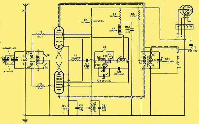
Fig. 1. - Theoretical circuit of the short-wave converter unit in which two heptode-type frequency changing valves are used in push-pull.
After this brief explanation of the factors that influenced the choice of the particular arrangement for the frequency changer in the short-wave converter illustrated here we can proceed to examine in detail the complete circuit as shown in Fig. 1. Provision is made for receiving over a waveband of 13.5 to 50 metres without changing the coils. This band is covered in two steps, with a small overlap between ranges one and two, which ranges are selected by means of ganged switches. As the two frequency changing valves are operated in push-pull for reception, the input circuit must be centre tapped; which entails arranging the coils in such a manner that the symmetry is preserved on both wavebands. This is achieved, in the present case, by winding the shorter range coil in two separate and equal parts, but on the same former. These are the coils L2 and L3. The additional loading coil for range two is on a separate former, with the windings joined between the inners of coils L2 and L3 and the centre point of the winding is earthed. On range one both halves of coil L4 are short-circuited, thus giving the required symmetrical arrangement with a centre tapping.
The aerial coil consists of a few turns tightly coupled to the range one coil and disposed equally each side of the centre of this coil. It suffices for both wave-bands. As the oscillator sections of the valves are joined in parallel we can adopt a much simpler and more straightforward coil assembly, and in this case the two coils are wound on one former, though they are not a continuous winding, as one of the padding capacitors is connected between them. The Hartley circuit shown makes for a simple coil construction and has the added advantage that it oscillates very easily.
Controls
A two-gang capacitor of 0.00015 μF each section, with both stator and fixed vanes insulated from the corresponding sections on the companion member, tunes the input and the oscillator circuits. These are C1 and C3 in the diagram. There is a small trimming capacitor joined across each, C2 for the input and C4 for the oscillator. The second mentioned is a semi-variable type, and only fixes the minimum capacity of the oscillator to trim this circuit at the lowest setting of the range. C2 is a small variable for trimming the input circuit and to make good any mis-tracking of the two circuits. Its inclusion in the controls is justified on the ground that accurate tracking is by no means easy to maintain throughout, though the two circuits can be made to run reasonably well by including series padding capacitors in the oscillator, but a small adjustment at different parts of the range to correct for minor discrepancies is well-nigh indispensable in a short-wave circuit of this type. Two padding capacities are needed for the oscillator. C9 is a 0.01 μF. fixed capacitor, and is used for tracking on range one. For range two, the higher band, a smaller padding capacitor has to be used, and this is provided by C8 joined between the two coils and which on range one is short-circuited by the same switch as short-circuits the additional coil L5. about 0.0008 μF is needed for padding range one, so that C8 has a maximum value of 0.001 μF and is a semi-variable or pre-set type.
High tension is fed to the oscillator anodes through a short-wave HF choke joined to the third turn from the anode end of coil L6. This is the range one coil, and the tapping holds good for the longer range also.
The only other part of the circuit that requires explaining is the output transformer. As the signal is applied in push-pull the output must be taken in the same manner, for which is used a transformer having its primary winding L7 tuned and centre tapped, whilst coupled to it is a second winding, L8, for feeding the IF frequency to the input of the broadcast receiver. The two windings are separated by an electrostatic screen, first to ensure that the coupling shall be only magnetic and so balance out the unwanted HF components flowing in the primary winding, and second to ensure equal capacity to earth each side of the centre tapping. Without this screening the presence of a lumped earth capacity at one end of the coil, for both primary and secondary are wound concentrically on a one-inch Paxolin former, would result in the two sections of the primary being out of balance. One end of the secondary joins to the aerial terminal on the set, this is marked Output + the other, Output -, goes to the earth terminal.
The screen voltage for the valves is derived from a potentiometer consisting of two fixed resistors R5 and R6 in an orthodox manner, whilst the grids of the tetrode portions are given a small negative bias by inserting a 150 Ω resistor R3 in the common cathode lead to the earth line.
The resistors R1 and R2, each of 250 Ω, in the grid leads of the tetrode sections are to suppress parasitic oscillations in the input circuit which may appear if the circuit is not perfectly balanced. In some cases it might be possible to reduce these to 100 Ω each, whereas if the two halves are badly out of balance through stray leakage or other causes, these might even require to be increased to about 500 Ω.

Fig. 2. The power supply for the converter is derived from a separate unit, the circuit of which is shown above.
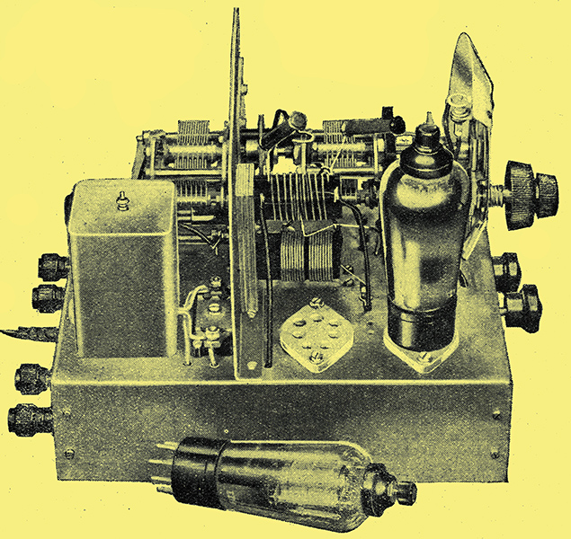
The converter derives its HT and LT from a separate unit, the circuit of which is given in Fig. 2. Incidentally, the chassis of this unit is exactly the same size as that of the converter. Dividing the apparatus into two parts allows for considerable latitude in the choice of a cabinet. They can be mounted side by side, or as a two-deck assembly, according to individual requirements.
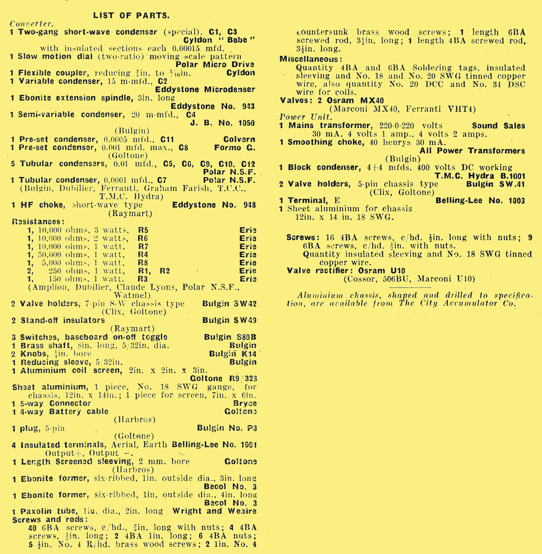
Parts List

Construction
Construction of the converter was covered in a separate part. Below is the diagram of the chassis dimensions.
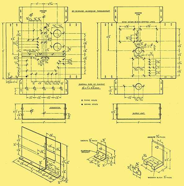
Dimensional drawings of the two chassis required for the short-wave converter and its power supply unit. Details are given also of the aluminium screens and of the two small brackets. Diameters of holes (in inches) are: A = ⅛ B = 5/32 C = ¼ D = 5/16 E = ⅜ F = 1.0 and G =1¼.
|