|
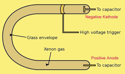
Basic construction of a xenon flash-tube.
A flash-tube, also called a flash lamp, is an electric arc lamp designed to produce extremely intense, incoherent, full-spectrum white light for very short durations. Flash tubes are made of a length of thin glass tubing with electrodes at either end and are filled with a gas that, when triggered, ionizes and conducts a high voltage pulse to produce intense light. Flash tubes are used mostly for photographic purposes but are also employed in scientific, medical and industrial applications such as lasers.
The flash lamp comprises a hermetically sealed glass tube, which is filled with xenon, and electrodes to carry electrical current to the gas. Additionally, a high voltage power source is necessary to ionize the gas. A charged capacitor is usually used for this purpose so as to allow very speedy delivery of very high electrical current when the lamp is triggered. (See fig. 1 above.) Flash tubes require high operating and triggering voltages and caution must be observed when using them.
The glass envelope is often made of fused quartz, borosilicate, or Pyrex. The electrodes protrude into each end of the tube. For low electrode wear the electrodes are usually made of tungsten, which has the highest melting point of any metal. Cathodes are often made from porous tungsten filled with a barium compound and the structure of cathode has to be tailored for the application. The cathode undergoes destruction from positively charged xenon ion bombardment. Anodes are usually made from pure tungsten.
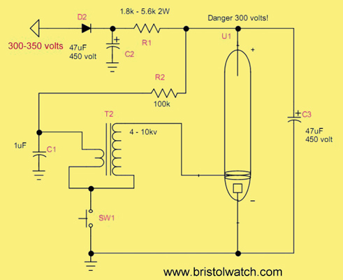
The main components of a flash-tube circuit
The main components of a flash-tube circuit are: a high voltage power supply, the flash-tube itself, a high voltage trigger transformers, and a photoflash capacitor.
The tubes I used required 300 Volts to operate correctly. One can use an inverter, a device that steps up a low voltage battery to a high voltage (this is used in cameras), or a voltage doubler circuit for a 120-volt AC line. I used a home-made inverter circuit using a 12-volt centre-tapped transformer as shown in the photos below.
Capacitor C1 is charges through resistor R2. When the switch is pressed C1 quickly discharges though T2 creating a high voltage pulse that ionizes the gas in the tube, causing C3 to discharge through the tube, thus crating a bright flash.
Note that while a standard electrolytic capacitor can be used, specially made photoflash capacitors should be used. They can withstand the high discharge rate. Resistor R1 must be used to keep the power supply from swamping and destroying the tube. In my setup C3 charges up to 330 Volts and discharges down to 100 Volts.
Using a photoflash capacitor that's too large can destroy the tube from overheating and thermal shock. The trigger transformer is usually matched to the tube.
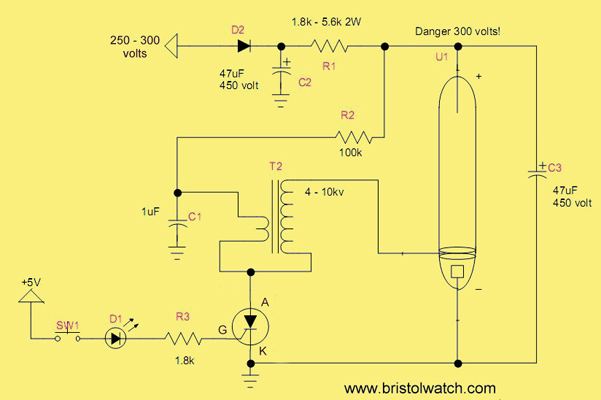
Using an SCR allows the use of low-voltage electronics to control the flash. Make a note of the gate sensitivity.
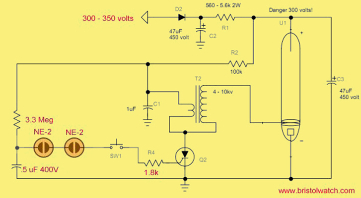
Another variation of triggering an SCR through one or two NE-2 neon lamps.
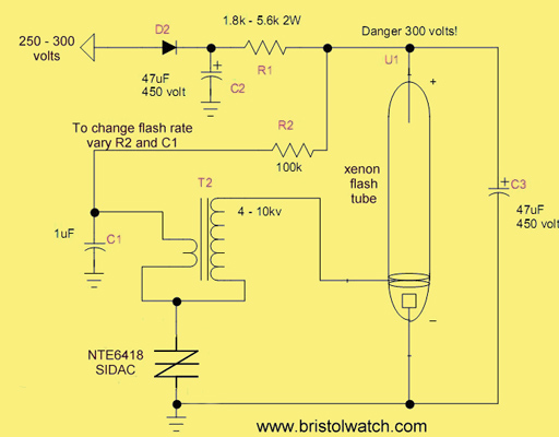
Here we use a Sidac. The flash rate is controlled by R2 and C1.
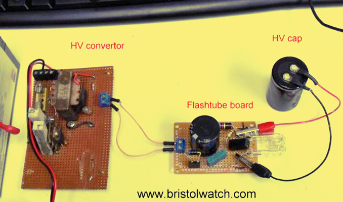
Experimental flash-tube test setup.
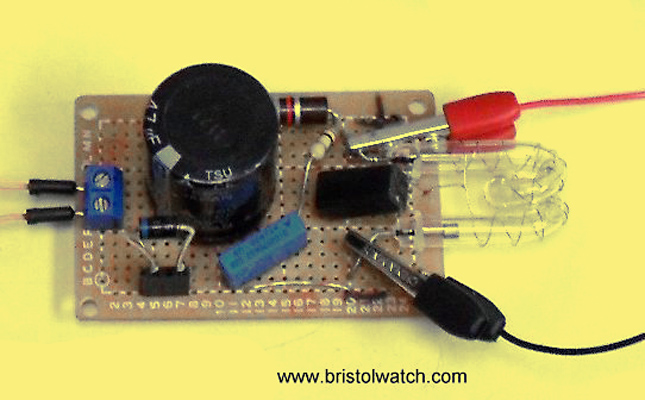
Closer view of the flash-tube board.
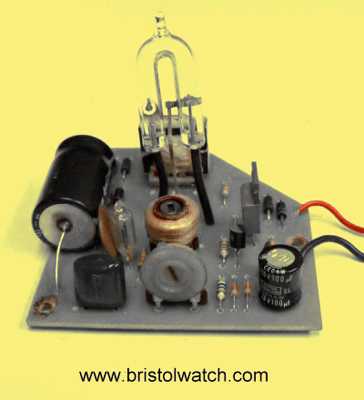
A board removed from a flasher used on a state truck.
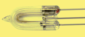
Horseshoe shaped flash-tube.
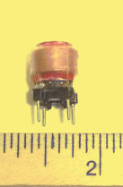
One type of trigger transformer.
|