|

Elements of the orbit of an artificial satellite (Reproduced, with acknowledgments, from Radio.)
There was great excitement in the world of radio on October 5 when it was learnt that the Russians had launched their first satellite. In spite of much previous discussion on the reception of satellite signals, the actual event took everyone by surprise. Observing stations were hastily improvised from existing equipment by amateurs and professionals alike. The BBC used their listening station at Tatsfield, the DSIR their radio research establishment at Slough, and the GPO their measuring stations at Baldock and Banbury. At the same time the radio astronomers at Cambridge and Jodrell Bank worked furiously to rig up equipment for precise position-finding measurements on the actual track of the satellite, while similar measurements were started immediately by the Royal Aircraft Establishment, Farnborough, and at Malvern by the Royal Radar Establishment. Between these official organizations and the many amateurs who made observations were bodies like the British Astronomical Association, whose Radio Section took recordings of the signals at their small station at Clacton.
Nobody in this country was prepared for the use of 20 MHz and 40 MHz as the transmission frequencies because it was expected that the American satellite, using 108 MHz, would be the first to be launched. This state of unpreparedness should never have existed, however, for the frequencies were published in the June, 1957, issue of the Russian journal Radio, which is available in this country, and were officially notified to the Royal Society in the following August. The June issue of Radio contained two articles (from the first of which our title is reproduced) mainly giving advice to amateurs for observing the satellite. The first begins:
'During the course of the International Geophysical Year it is intended in the USSR to launch a number of artificial satellites of the earth, equipped with radio-transmitting apparatus. Radio observers of the signals from these satellites will make it possible to obtain fresh data regarding the structure of the ionosphere and to determine with accuracy the size, shape and position of the orbits of the satellites, and also to draw conclusions regarding the processes and occurrences taking place in the satellite during the course of its flight'.
The second article mentions the use of two radio transmitters 'having frequencies of approximately 20 MHz and 40 MHz, and the power of the transmissions will be approx. 1W. These transmitters will operate continuous over a long period (this period being limited by the sources of electrical power contained in the satellite). Consequently, the special radio reception points as well as radio amateurs throughout the whole of the territory of the Soviet Union as well as countries abroad will be able to receive time and time again the radio signals transmitted by the equipment mounted in the satellites.
'The signals given out by the transmitters in the satellites will be similar to telegraphic strokes having a length of from 0.05 to 0.7 seconds. The transmission will be arranged to proceed in such a manner that one transmitter will be heard during the interval in the transmission of the other'.
Of course, we know now that the actual pulse duration was approximately 0.3 second, on both frequencies in the first satellite and on 20 MHz in the second satellite. Moreover the frequencies proved to be 20.005 MHz and 40.002 MHz, the increments of 0.005 and 0.002 being made probably in order to generate audio beat frequencies of 5 kHz and 2 KHz with local oscillations of 20 MHz and 40 MHz at the ground receiving stations. We know also that the 23-inch aluminium-alloy sphere of the first satellite carried four projecting rod aerials of 2.4-2.9 metres in length, which were folded back against its body during the flight in the rocket but afterwards swung out on swivels to their correct positions. The 184-lb weight of Sputnik 1 was said to have been largely made up by the weight of the batteries, which have been estimated as supplying a power of 10-30 Watts.
The second satellite is reported by the Russians to contain a great deal more telemetering equipment for measuring temperature and pressure, cosmic rays, electromagnetic radiation from the sun in the short-wave, ultra-violet and Rontgen regions, and also various physiological parameters from the passenger dog. Very little is known at present on the precise method of modulating all this information on to the radio frequencies, but it is likely that some time-sharing system is used, even though two carriers are available.
Pulse Recurrence Frequency
In Sputnik 1, it was stated by the Russians that the mark/space ratio of the pulses was modulated and also 'the frequency of the telegraphic messages'. Whether this meant the radio frequency or the pulse recurrence frequency was not clear. The BBC at Tatsfield noted a gradual increase in PRF from 108 pulses per minute to 150 per minute before the keying on 20 MHz stopped altogether on October 7. In the second satellite the keying on 20 MHz stopped on November 3, leaving both transmissions in continuous operation.
Most people are by now familiar with the general nature of the orbits of the two satellites, but before passing on to the radio astronomy measurements it may be as well to look briefly at the basic astronomical parameters involved. For this purpose we quote from the June issue of Radio mentioned earlier.
Elements of the Orbit
'In consequence of the ellipticity of the orbit, the height of the satellite from the earth will vary during one revolution; the point at which the height of flight is maximum is called the apogee, whereas the point of minimum height is called the perigee. In order to be able to determine completely the shape, size and position of the orbit of such a satellite, it is sufficient to have a knowledge of five different magnitudes (see diagram at start of this article): the height of the perigee, the height of the apogee, the inclination of the orbit (i.e. the angle which the plane of the orbit makes with the plane of the equator), the distance between the nodes (i.e., the angle which the line crossing the orbital plane and the equator makes with a given celestial line also lying in the plane of the equator - the line fixed by the vernal equinox) and, finally, the angular distance between the perigee and the node'.
'These magnitudes are called the elements of the orbit; they provide the fundamental data required for determining the number of revolutions within a 24-hour period. They will have to be determined as many times as possible in order to ascertain the variations which will occur in the satellites orbit before it reaches the point at which it begins to fall rapidly and finally disintegrates.'
'. . . . The orbital plane of the satellite does not share in the rotation of the earth, whereas the observers, who are located on the surface of the earth, naturally follow the rotation of the earth from west to east. . . . During the time of one rotation of the artificial satellite (which will probably be approximately 1.5 hours) an observer located on the equator would be moved 2500 km towards the east, whereas an observer situated at a latitude of 45° would be moved 1760 km and an observer situated at a latitude of 60° would be moved 1000 km. The northern and southern limits of observation are determined by the inclination of the orbit of the satellite, which defines how far the satellite will move either to the north or to the south. During every period of twenty-four hours the artificial satellite will make 16 revolutions round the earth and in so doing will make, as it were, a regular pattern or network over the earths surface. The satellite to be launched in the USSR will travel in such a manner that it will pass over practically every inhabited region of the earth'.
'The time during which it will be possible at any given point on the earths surface to pick up radio signals from the artificial satellite will be determined by the speed of the satellite (8 km per second) and the greatest distance at which it is possible to receive the signals transmitted. The time for receiving signals will probably last for several minutes'.
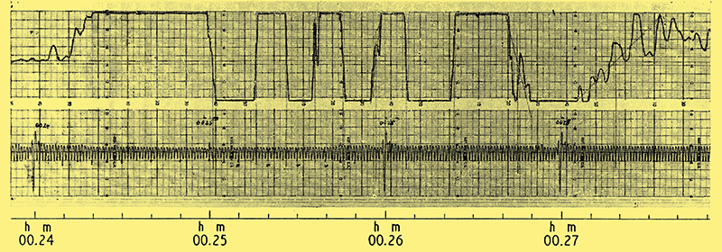
Record of interferometer output taken from Sputnik 1s 40-MHz transmission at Cambridge on October 6. The lower waveform is a timing reference, and the 1-minute and 10-second intervals are shown on the scale below the chart.
The several minutes in the last paragraph is illustrated in practical terms above, which is one of the first recordings of Sputnik 1s signals taken at the Mullard radio astronomy observatory at Cambridge. It was obtained at night in the first hour of October 6, and occupies a total time scale of nearly 5 minutes. This record is actually the output of a receiver fed from interferometric type of aerial system of the kind already described in Wireless World.

Schematic of the 40-MHz interferometric aerial system at Cambridge. lt was actually modified from a 38-MHz radio telescope used on radio stars.
Two spaced dipoles are used, as shown above, giving an interference pattern consisting of multiple lobes as in the polar diagram below.

General form of the interference-pattern type of polar diagram produced by the spaced aerial system above.
A source of signals like a satellite passing through this pattern therefore produces an output from the receiver which goes through maxima and minima of the kind shown on the record.
At any particular height above ground a plan view of the minima between lobes takes the form of a hyperbolic pattern, as shown below.

Plan view of a horizontal plane cutting through the interference pattern from the previous diagram at a particular height. The hyperbolae represent the minima between lobes. The calculated points are fitted to these hyperbolae to give the track of the satellite.
The actual positions of these lines are established of course, from a knowledge of the geometry and geographical positioning of the aerial system (which is arranged on an accurately surveyed east-west line). Similar hyperbolic patterns can be drawn for all heights above ground. Thus, from the time intervals between minima on the record and the roughly known velocity of the satellite (derived from the period of rotation), it is possible to calculate a series of points with particular spacings on a straight line that will fit on to one of the hyberbolic patterns. In this way the track of the satellite relative to the aerial system can be found, as shown above, while the hyperbolic pattern in use will give the height.
Measurements of this kind were made not only at Cambridge (on the 40 MHz transmission) but also by the Royal Aircraft Establishment and the Royal Radar Establishment, both of whom used crossed interferometric aerial systems. All three establishments in addition took measurements of the changes in frequency produced by the Doppler effect. The results were used for calculating the velocity of the satellites and also for obtaining ranges from which the tracks could be obtained for correlation with the interferometric methods. To explain how the Doppler method is used to obtain this velocity and range information we again give a direct quotation from the Radio articles.
'The Doppler effect is concerned with the variations in frequency which are produced when the transmitter and receiver approach one another or move further apart from one another. The known principle is that when the source of the waves and the receiving station approach one another the frequency observed is higher than the emitted frequency. Conversely, if the transmitter and the receiver are receding from one another, the frequency as received will be lower than that emitted.'
'The speed of approach or recession of the satellite will vary according to a special pattern on account of the elliptical shape of the satellites orbit. It will readily be seen that it is not merely a question of approaching in a straight line at constant velocity and then passing the observer station and receding at the same constant velocity. The speed in relation to the receiving station will vary according to the angle of the particular section of the orbit in relation to the point of observation. When the angle between the direction of movement of the satellite and the direction of the waves received by the receiving station is greater than 90°, the satellite commences to recede from the receiver; the velocity of this motion of recession gradually increases and reaches its maximum before the signals cease altogether. At first the signal will be found to have its maximum frequency, and then when the satellite gets near to the reception point the frequency will decrease somewhat, and finally, when the satellite is moving away from the observer, the frequency will decrease down to the minimum. This is shown in diagrammatical form below'.

Curves showing change of received frequency with time produced by the Doppler effect as a satellite approaches and recedes from the receiving station. The three curves represent transits at different ranges. The transmitted frequency is 40.002 MHz. (Reproduced from Radio.)
'The period during which the frequency change due to the Doppler effect will be noted will last for two to three minutes and consequently it is essential to be ready for measuring any differences before the satellite comes into range'.
At Cambridge the frequency changes were measured by heterodyning the incoming satellite frequency of 40.002 MHz with a local 40 MHz oscillator and comparing the resultant audio beat note with an equivalent signal from a calibrated variable AF oscillator. The comparison of audio frequencies was done by ear and by keeping a Lissajous figure stationary on a cathode-ray tube display. Readings were taken at 3 second intervals, to obtain graphs of the kind shown in the Russian diagram. As indicated, the total frequency change on 40.002 MHz was about 2 kHz, taking place over periods of about 2 to 10 minutes or more, depending on the range. It will be noticed that the frequency transition occurs rapidly at short ranges and slowly at long ranges.
From the Doppler law relating the rate-of-change of the curve to the distance of the observer it is possible to calculate the actual range of the satellite on a particular transit. Measurements on two successive transits will then give the track and height by triangulation. At Cambridge the results of these Doppler observations were combined with those of the interferometric methods, and, as is well known, figures for the various parameters illustrated in the first diagram were obtained with extreme accuracy. The inclination of the orbit was found to within ±10 minutes of arc, for example, the period of rotation to within ±0.3 seconds and the heights at the apogee and perigee to within ±10 kilometres. This was a remarkable achievement.
When the signals from Sputnik 1 ceased, greater attention was naturally focused on the radar observations. These were made at the Jodrell Bank radio astronomy establishment, using the giant 250-ft diameter radio telescope, and at the Royal Radar Establishment, Malvern, with a new 45-ft radio telescope.
Ranges by Radar
Jodrell Bank operated with two radar transmitters. The first, on 36 Mhz, had a peak power of 10 kW, a pulse duration of 150 μsec and a PRF of 75 per second. The second, working on 120 MHz, also had a peak power of 10 kW, with a pulse duration of 2 mS and a PRF of 10 or 20 per second. W/hen observations were made on the orbiting rocket belonging to Sputnik 1, the range of detection on 120 MHz was limited only by earth curvature, and adequate signal/noise ratios were obtained at ranges of over 900 miles. The pencil beam of the 250-ft paraboloid has a calculated angular width of about 2°-3° at 120 MHz and about 8° at 36 MHz, while the calculated power gains at these frequencies are respectively 6,500 and 600. A much finer pencil beam was used at Malvern - only 0.5° in angular width - obtained with a frequency of 3 GHz. Here, ranges of over 800 miles were reported on the rocket.
At the DSIR station at Slough and the BBC station at Tatsfield, some interesting observations were made on the maximum ranges at which the satellite signals could be heard. With Sputnik 1 the signals were received for about 30-35 minutes on each satellite transit, which suggested that they were coming from far beyond the optical horizon (about 2,000 miles range) where one would not normally expect to hear them. In fact the range was about 4,000 miles. The probable explanation for this is, of course, that the waves from the satellite transmitter were retracted by the ionosphere (through which they would pass from outside) in such a way as to bend them round the curvature of the earth. The ionosphere was also no doubt responsible for the curious short burst of 20 MHz which usually occurred before the main signal was received. At Slough most of the measurements were, in fact, done on 20 MHz because of the greater effect of the ionosphere on that frequency. At Cambridge, on the other hand, they used mostly 40 MHz in order to avoid the inaccuracies introduced by the ionosphere in the position-finding measurements.
Signal Strengths
Many different aerials were pressed into service by the BBC at Tatsfield - open-wire types, horizontal rhombics, double rhombics, vertical 'V's, short-wave stacks - while receivers were standard communication types with beat frequency oscillators. Both signal-strength and frequency measurements (for Doppler calculations) were made. With the first satellite the signal strength was occasionally as high as 35 μV/m during the first few days, but most of the time was only just above noise level. The signal from the Sputnik 2 was much weaker, as might be expected from the greater range, and was generally less reliable.
The variations recorded in the signal strength were, in fact, one of the most complex aspects of the satellite transmissions. There were several different periodicities in these fluctuations and a number of possible reasons for them. The report from Cambridge in Nature mentions three likely effects:
- rotation of the radiation patterns of the satellites aerials by the spinning of the satellite;
- changes of polarization in any plane-polarized component of the transmitted signal also produced by the spinning of the satellite;
- changes of polarization caused by Faraday rotation in the ionosphere resulting from the earths magnetic field.
The June issue of the Russian journal Radio, incidentally, comments on the expected variations as follows:-
' . . . At some points in its movement the aerials of the satellite will be located in such a way that the wireless waves reaching the aerial of the receiving station will have a circular polarization. At other times the aerials fitted to the satellite will be pointing straight in the direction of the receiving aerials of the observer station, so that the waves reaching the receiving station have a linear polarization'.
To distinguish between these possible effects the Cambridge observers fitted up receiving aerials with mutually perpendicular planes of polarization. It was then found that the fading patterns on the two aerials differed in phase by π/2, showing that the rotation of the plane of polarization was the most important cause of the signal fluctuations. To distinguish between the rotation due to spinning and that due to the Faraday effect, they made observations of the fading periodicities on both 20 MHz and 40 MHz. The significance here is that the Faraday rotation is proportional to the square of the wavelength, and, therefore, produces more rapid fading on 20 MHz than on 40 MHz. The fading due to the spinning of the satellite, however, is independent of frequency. Curves have been plotted of several of the periodicities of fading against GMT for both the 20 MHz and the 40 MHz signals. The two curves for a particular satellite transit coincide more or less exactly if the periodicity scale on 20 MHz is arranged to represent values four times as big as those on the 40 MHz periodicity scale. In other words, at twice the wavelength the fading periodicity is quadrupled - which shows that the periodicity is proportional to the square of the wavelength and supports the hypothesis that some of the fading is, in fact, due to Faraday rotation.
The Cambridge observers also say in Nature that their fading periodicity measurements indicate that Sputnik 1 was spinning at seven revolutions per minute. It has been noticed that this spin fading is accompanied by a marked irregularity in the Doppler curves. The effect, they say, may be caused by the periodic reversal of the sense of the circularly polarized component of the transmission as the satellite spins.
The Faraday rotation measurements, among others, are likely to be of great value in the studies of the ionosphere which form part of the International Geophysical Year programme. As an example, the electron density of the ionosphere is of great interest. The angle of rotation of the plane of polarization of the transmitted wave is determined by the total number of electrons along the 'line-of-sight' path to the receiving aerial. Consequently, as the satellite moves along its track the length of the path through the ionosphere changes and also the number of electrons. This in turn produces a change in the angle of rotation of the polarization, giving an alteration of signal strength at the ground receiving station. Knowing the track of the satellite and the inclination of the earths magnetic field to the 'line-of-sight' path, it is possible to find the rate of change of electron content along this path.
Ionospheric Refraction
The existence of radio transmitters above the ionosphere at varying heights and at varying angles of elevation make possible other types of investigations. To quote again from Radio: 'It must also be borne in mind that the signals received from the artificial satellite will have had to pass right through the ionosphere and in so doing will doubtless be subjected to refraction, both on entering and on leaving the ionosphere. . . . In turn, the amount of this refraction will depend upon the wavelength, so that the data received from all sources regarding the reception conditions of both signals on their different wavelengths will, when properly collated, supply further information regarding the structure of the higher strata of the earths atmosphere'.
As an example of this, the Cambridge workers mention in Nature measurements which allow the angle of refraction of the waves to be found at different angles of elevation. The angles of arrival of the 20 MHz and 40 MHz signals are measured by comparing the apparent times at which the source crosses the minima lines of similar interferometers working on these respective frequencies.
Preliminary measurements of this kind have already been done at Cambridge. They mark the beginning of a new era of scientific study, which has only been made possible by the tremendous technical achievement of planting these radio stations in space beyond the ionosphere.

The 250ft steerable radio telescope used at Jodrell Bank Experimental Station for observing the satellites by radar techniques.
|