|
The following is an extract from the review published in Wireless World.
Microwave Valves
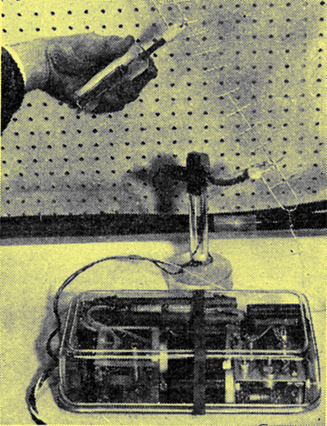
Mullard miniature S-band magnetron and modulator. The miniature Yagi aerials and neon indicator used for demonstrating transmission and reception are also shown.
The weight of an experimental miniature pulsed 200 Watt S-band (2850 MHz) magnetron shown by Mullard Research Laboratories was only 3.5 oz including the associated magnet. The 2 kV, 1 A pulse input was obtained from a transistor modulator. A 500 Hz square-wave oscillator feeds a transformer to give an output of 2 kV. This is voltage doubled, rectified, and fed to a five-section line whose other end is matched to the magnetron. The 500 Hz oscillator also triggers a spark gap at the input end of the line so as to produce a discharge pulse which travels down the line, and whose voltage is shared between the magnetron and the line.
Frequency shifting of a microwave signal was illustrated by Mullard Research Laboratories. Phase modulation of the output of an LA9-3 X- Band (9 GHz) travelling wave tube by sawtooth or sine-wave modulation of the helix voltage was shown. With sine-wave modulation a number of sidebands are produced, at least 6dB down on the unmodulated signal. With sawtooth modulation, if the amplitude is such as to produce a maximum phase change of 2π, the fundamental and all sidebands but the lower first are almost entirely suppressed, as described by Cummings in Proc. I RE for February 1957. Thus an almost pure shift in the frequency by an amount equal to the sawtooth frequency is obtained. Moreover, almost the full gain of the TWT is still realized.
Oscillograph Tubes
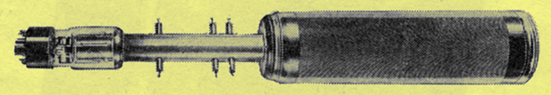
20th Century travelling wave deflection CRT.
The general trend of development in instrument CRT's is towards higher writing speeds and greater resolution. Tubes capable of displaying frequencies up to 500MHz are becoming almost commonplace nowadays and spot sizes of less than 0.001 in are not unusual. Above 500 MHz the transit time of the electron beam through the deflection plates is the limiting factor on frequency response, and it becomes necessary to use special techniques like the travelling-wave deflection system mentioned last year (June, 1957, issue, p. 283). A tube with a similar deflection system has been developed by 20th Century Electronics for photographic recording of millimicrosecond transients, and its travelling wave system has an upper frequency limit of 3,000MHz.
Whereas the tube described last year had just a single helix for the travelling wave, the 20th Century tube is distinguished by a balanced pair of helices between which the electron beam passes. This gives greater deflection sensitivity and less defocusing of the spot by the deflection system.
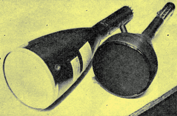
Ferranti two-colour radar tube (left) and transparent-screen tube with black backing.
Among the more conventional oscillograph tubes, the Ferranti type 5/63 is particularly interesting because of its high deflection sensitivity of 2.5 volts/cm (with 10 kV on the anode) and a so-called beam lever electrode which can be used to vary the sensitivity over a 2:1 range by application of voltages between zero and a few hundred volts.
Electronic Tubes were showing a low-consumption 3-inch tube for battery-operated portable oscilloscopes. The HT voltage required is only 1,000 Volts, which can be obtained from a transistor DC/DC converter, and the heater consumption has been reduced to 1 Watt.
Transparent Screen CRT shown in experimental form by Ferranti has been developed for high-definition work in radar or television. The fluorescent screen is not applied to the face plate in powder form but evaporated on to it. Calcium tungstate is used as the phosphor because it enables the baking process necessary to diffuse the activator to be done at a lower temperature than with other materials. Apart from giving higher resolution (because of the finer grain of the evaporated phosphor) the transparent material makes it possible to apply a black backing to the screen. This does not reflect room illumination like the usual white powder screens and so the contrast of the picture is greatly improved. The tube has a triode electron gun and operates with 20kV on the anode.
Two Colour Radar Tube, also exhibited by Ferranti, has two phosphors, one of which lights up blue with relatively few sweeps of the spot while the other lights up magenta after a greater number of sweeps. This makes it possible to distinguish moving objects from fixed objects by colour differentiation. A fixed object produces continuous responses on a given piece of phosphor, which therefore lights up magenta, while a moving object only permits a few sweeps over a given piece of phosphor and, therefore, appears blue. The tube, type 6/61XM, also helps to distinguish between signal and noise by virtue of the repetitive nature of the signal.
Storage Viewing Tube, shown by English Electric, has its screen continuously energized by a flood beam passing through a dielectric mesh. A writing beam controls the surface potential of the mesh and so modulates the flood beam current reaching any part of the screen. A much higher luminous output can be obtained than from a conventional CRT. The persistence of the trace can be varied from a fraction of a second to several minutes by applying a positive pulse of controlled duration to the metal supporting the mesh.
CRT Resolution measurement system devised by the Royal Radar Establishment is based on a new parameter called spatial frequency response. It avoids the uncertainties resulting from the common practice of specifying resolution in terms of spot size (arising from the spots lack of sharply defined edges and unknown brightness distribution). The system actually measures the extent to which a tube can reproduce video signals applied as intensity modulation to a timebase. In this respect it is similar to the television practice of stating resolution in terms of so many lines. A 100 kHz sine wave of constant amplitude is used to modulate the spot brightness, and the timebase speed is varied to give different numbers of intensity cycles along the trace - or different spatial frequencies as they are called. At each spatial frequency the amplitude of the light intensity cycles reproduced on the screen is measured by a photoelectric method and the results are plotted to give a curve similar to a frequency response characteristic. At zero and low spatial frequencies the geometry of the spot does not prevent the tube from showing the full amplitude of the light intensity cycles, and this condition is termed 100 per cent modulation. At higher spatial frequencies the spot size becomes significant in relation to the finer displayed patterns and the tube is increasingly unable to reproduce the full amplitude of the light intensity cycles. The amplitudes measured by the photoelectric system are therefore plotted as percentages of the full 100 per cent modulation.
|