|
After outlining the technique of power rectification as employed in normal broadcast sets, the author goes on to describe special rectifiers and circuits for high-power receivers, amplifiers, television sets, etc.
The usual mains-driven set consumes, all told, an anode current of the order of 60 to 80 mA at about 350 volts. This voltage is higher than is required for the receiver itself, but the excess voltage is lost across the field winding of the speaker, which is normally placed in series with the anode current supply to all valves. A little more voltage is lost in providing bias for the valves.
The rectifier normally chosen for this duty is a full-wave rectifier which will deliver 120 mA at 350 to 360 Volts, being rated for 350-0-350 volts RMS on its anodes. Such a valve, a few years ago, would quite certainly have been classed as a 'heavy-duty' rectifier; at the present time one would rather regard it as the biggest of the 'normal-duty' valves, and look upon the heavy-duty class as beginning with valves capable of, delivering anode current at some 500 Volts.
In accordance with a scheme of partial standardisation introduced some years ago, all valve-makers now offer a full-wave rectifier rated at an AC anode voltage of 500-0-500, and capable of delivering a continuous current of 120 milliamps. This is sufficient to run a single output valve of the 400 Volt 63 milliamp class, and of providing at the same time both the necessary excess voltage for energising a loud-speaker field and the current required for the rest of the receiver. An output stage of this type will deliver some 5 to 6 Watts to the loud speaker. This is a very generous output for ordinary domestic use, and is adequate for a public-address system to be used in a small hall.
Two output valves of this class, if over-biased a trifle and run in push-pull will give more than double this output; a rectifier of the type mentioned will just provide the necessary current for the output stage and the loud-speaker field, but will have no spare milliamps. for the rest of the receiver. In such a case an auxiliary HT supply, providing perhaps 50 mA at 250 Volts, is generally used for earlier valves, this is preferable to duplicating the high voltage rectifier, as it separates the output stage from the rest of the equipment and does away with the need for voltage dropping resistances and high-voltage capacitors in the early part of the set. It must not be forgotten in considering these rectifiers, that the maker's rating concerns the RMS value of the alternating voltage applied to the anode. The actual DC voltage developed, even at full load, is appreciably in excess of the AC rating.
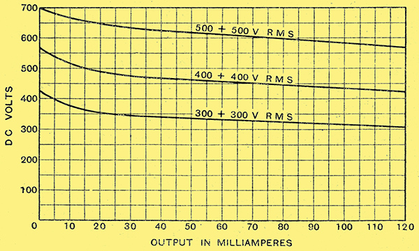
Fig. 1. - Regulation curves of Mazda UU120/500 rectifier with 4 μF reservoir capacitor. Note that DC output voltage, even at full load, exceeds RMS value of the AC applied.
This is shown in Fig. 1, which gives the regulation curve of the Mazda UU120/500 with a reservoir capacitor of 4 μF the output is about 575 Volts at 120 milliamps, rising a little at lower currents. The Cossor 460BU, the Marconi or Osram W14, and the Mullard DW4 are similar.
Besides theses directly heated valves, indirectly heated rectifiers are obtainable in the same rating. These are a newer introduction, and are very suitable for use in cases where some or all of the valves in the set are also indirectly heated, since the anode voltage is not applied until all the valves are drawing current. The Marconi or Osram MU14, the Mullard IW4, the Hivac UU120/500, and the Standard-R3 belong to this category.
For still larger outputs, running up to 250 milliamps at 500 Volts, a rectifier such as the Marconi or Osram U18 will probably be chosen. This will run a push-pull pair of 400 Volt 63 milliamp valves, and still have plenty of reserve for the rest of the set. Alternatively, it would drive an output stage consisting of four such valves in parallel push-pull, from which the very respectable output of some 25 Watts may be expected in normal circumstances.
It it is not called upon to energise the speaker, which normally involves the loss of about 100 Volts, it will satisfactorily provide anode current (but not grid-bias) for a pair of DA30 type valves used as a low-load push-pull pair, or even to a pair of DA60 valves as ordinary Class A amplifiers in push-pull or parallel. These valves take 120 milliamps each at 500 Volts. In either of the last two arrangements, it is suggested that the speaker-field can profitably be excited from a small separate rectifier, this also supplying the rather high grid-bias (round about 130 Volts), which these large output valves require. A circuit of this type is shown in Fig. 2.
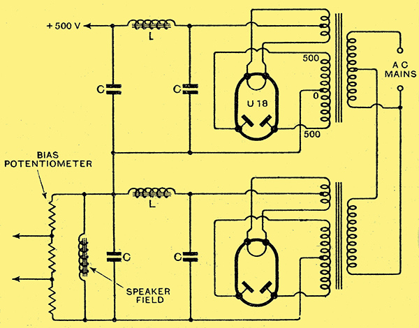
Fig. 2. - Circuit showing high-voltage rectifier for anode current, with auxiliary low-voltage rectifier (about 150 Volts) supplying field of speaker and also grid bias.
In setting up a circuit of this kind care should be taken that the reservoir capacitor is not too, large, or the valve, if called upon to deliver a steady current of the maximum value for which it is rated, may pass a dangerously high peak current. It is also important that the smoothing chokes should be adequate for the very large current they are called upon to carry. This means a large core, gapped to prevent magnetic saturation. Since, in addition the resistance has to be fairly low to prevent undue loss of Volts (one Volt for every four Ohms) at the high current the choke has to pass, the winding must be of comparatively few turns of thick wire. This, like the gap, necessitates an increase in the total size of the core. Those who have never met a smoothing choke of 20 Henrys designed to carry 250 milliamps at a voltage drop not exceeding 25 Volts will be taken aback at its bulk and weight - and probably at its price, too.
For PA for Cinema Work
It is not very often that one requires higher voltages and currents than those given by the valves just described, which are the biggest of the thermionic rectifiers of ordinary type. But for large public-address systems, or cinema work, it may be desirable to run an output stage consisting of one or possibly two valves such as the Marconi or Osram DA100 or the Mazda ES100. These, as their name implies, are output triodes of 100 Watts dissipation; they take their power in the form of an anode current of 100 mA at 1,000 Volts, and require a bias of nearly 150 Volts.
For such power consumption as this the thermionic rectifier is best deserted for one of the mercury-vapour valves such as the Marconi or Osram GU1 or GU5, or the Ediswan MU1 or MU2. These valves have a very heavy filament, consuming 3 Amperes at 4 Volts, and differ from an ordinary rectifier in being 'filled' with mercury vapour instead of being completely evacuated. When the voltage applied to the anode exceeds the ionisation voltage of mercury - about 13 Volts - the electrons from the cathode ionise some of the mercury atoms-in the bulb. The positive ions so produced neutralise the space-charge round the cathode and allow all the emitted electrons to reach the anode, so far as the external resistance of the circuit permits.
This implies that the internal resistance of a mercury-vapour rectifier, once the discharge starts, is extremely small. The total energy dissipated in the bulb, and therefore the heat developed, is in consequence very little more than the filament wattage; a small bulb can therefore be used for a rectifier dealing with considerable power. With so low an internal resistance it is evident that if at any time the load-resistance is removed (HT positive shorted to earth, etc.) outrageously high currents will immediately flow. If the current rises so far that the emission of the valve, and not the circuit resistance, is the sole limit to the current, mercury ions will bombard the cathode with such energy as to cause the destruction of the emitting coating within a few minutes. It is therefore desirable to include either a fuse or a limiting resistance in series with the anode circuit of the rectifying valve.
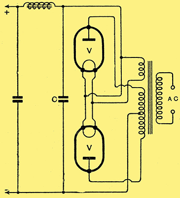
Fig. 3. - Standard type of smoothing circuit. Not suitable for mercury-vapour rectifiers, owing to possibility of surges of current into the reservoir capacitor C.
If the ordinary smoothing circuit of Fig. 3 is used, there is nothing to limit the flow of current into the reservoir capacitor. To switch the HT on to the anodes with the reservoir capacitor discharged would result in a current of e several amperes - perhaps several hundred amperes - for a fraction of a second. These sudden surges can be satisfactorily prevented by using a filter with a choke input, as suggested in Fig. 4. The makers recommend that when using GU1 valves L should not be less than one Henry, while with the higher voltages applied to the GU5 valves the value of L should not fall below some 9 Henrys.

Fig. 4. - Smoothing circuit with input choke L. With mercury-vapour rectifiers at V, this circuit prevents sudden surges.
Besides a rise in current, there is another way in which the current flowing can equal the full emission from the cathode; that is by a fall in emission. If this occurs at the end of the valve's life, no harm is done the valve is dying, anyway, and one does not mind delivering the coup de grace. But if the emission falls through inadequate filament current the cathode bombardment will again occur, and will probably destroy, and certainly damage, the valve. Full filament voltage must therefore be carefully maintained.
For just the same reason the anode voltage must not be applied until the cathode has had full time to warm up. Either the user must switch on the filaments, wait for a minute or two, and then switch on the HT, or he must fit a thermal-delay switch to perform the delayed switching automatically. Such switches are obtainable from several makers; the vacuum - enclosed Ediswan switches (DLS/1 a nd DLS/10) are particularly attractive. Like other delayed-action switches, they depend on a bi-metallic strip built up from two metals which expand unequally on the passage of current through a heater. The only exception for the need for delayed switching is when the current to be taken from the rectifiers is small in the case of the Marconi and Osram GU1 and GU5 valves it is permissible to switch filament and anode voltage simultaneously provided that the total current to be drawn does not exceed 60 milliamps per valve, though with delayed switching each is capable of delivering up to 250 milliamps at voltages up to 1,180 in the case of the GU1, rated at 1,000 Volts RMS, and 1,260 Volts in the case of the GU5, rated for 1,500 Volts RMS. The lower figure in the latter case is due to the need for using a choke of higher inductance at L (Fig. - 4).
Advantages of Mercury Rectifiers
A pair of GU5 valves, delivering up to 500 milliamps at 1,280 Volts, will comfortably provide anode current and bias for four DA100 valves in parallel-push-pull, giving an undistorted output that is probably not far short of 150 Watts. This will drive ten to twenty speakers of the ordinary 12-inch type at not far short of the maximum power they can handle without discomfort.
These mercury rectifiers, owing to their very low internal resistance, are very desirable for use whenever the load is likely to fluctuate rapidly. For any form of Class 'B' or quiescent or semi-quiescent push-pull output stage, a power unit including mercury-vapour rectifiers is almost essential if the rapidly changing current demands are not to cause corresponding changes in anode voltage. It need hardly be pointed out that in such a connection the resistance of the smoothing chokes must be kept as low as possible, as must the resistance of the mains transformer windings.
For operating a cathode-ray tube high voltages are necessary, but the current taken is quite small. For this purpose the thermionic rectifier, suitably designed, is very well fitted. The Marconi or Osram U16 and U17, the Cossor SU2130, and the Mullard HVR1 are all of this type.
Essentially they are half-wave rectifiers of quite ordinary type but having their single plate brought out to the top cap of the bulb for the sake of providing adequate insulation against the very high voltages used. The HVR1 will take up to 6,000 Volts RMS, and is rated to deliver up to 5 milliamps continuously. The U16 is a similar valve, rated for 5,000 Volts RMS, and handling currents up to 2 milliamps. Where larger currents are needed the U17, taking 2,500 Volts RMS and yielding up to 30 milliamps, is more suitable.

Fig. 5. - Resistance-capacity smoothing for low-current high-voltage unit suitable for cathode-ray tubes.
In all these cases it is usual, since the current is comparatively small, to use resistance-capacity smoothing in a circuit such as that of Fig. 5. The voltages and currents available from the U16 and U17 valves are shown in Fig. 6, and give a good idea of the outputs that can be had from valves of this class.

Fig. 6. - Regulation curves of U16 and U17 rectifiers. Note that in the case of the U16, but not the U17, the voltage-drop in the smoothing circuit of Fig. 5 is taken into consideration.
Mazda produces a mercury-vapour rectifier, the MU2, for similar work. This may have applied to it up to 4,000 Volts RMS, and will give up to 5 milliamps continuous. For this low-current use delayed switching is not required, though if this precaution be taken the valve can be turned to other uses and employed to deliver a higher current at a lower voltage. Besides the vacuum and the mercury-filled valves, a metal rectifier may be used for cathode-ray work. These are available from the Westinghouse Company in two forms, known by the letters J and H. The former rectifiers give a maximum output of 2 milliamps, and may be used as simple half-wave rectifiers for output voltages up to 1,400 Volts. Still higher outputs, up to 3,000 Volts, may be had by arranging them in pairs in the voltage-doubling circuit of Fig. 7, while the same circuit using five 1,400 Volt rectifiers in series on each side will enable outputs up to 15,000 Volts, still at 2 milliamps, to be obtained. It is necessary to use one rectifier on each side for every 3,000 Volts required.
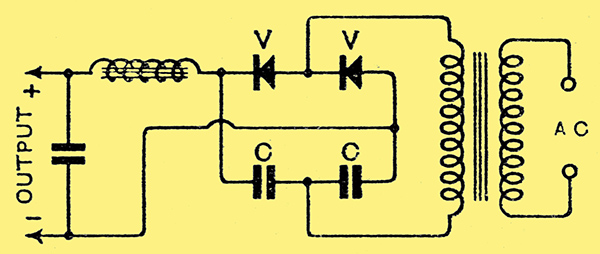
Fig. 7. - Voltage-doubling circuit for high voltages from metal rectifiers: C, C are the two 'voltage-doubling' capacitors, each of which acts as reservoir capacitor for one rectifier.
The voltage-doubling or reservoir capacitors do not need to be large, for the current drawn is small; for single-wave rectification at 1,400 Volts 0.5 μF is recommended by the makers, this capacitor being doubled or halved if the output voltage is halved or doubled. For voltage-doubling each of the two capacitors has this value.
The H-type rectifier is rated at a continuous output of 10 milliamps; the largest of them gives up to 650 Volts in the half-wave or 1,300 Volts in the voltage-doubler circuit. The reservoir capacitors recommended are 0.5 μF for 650 Volts half-wave, or 0.25 μF each for the 1,300 Volts. As with the J-type, higher voltages can be obtained by putting two or more rectifiers in series, reducing the capacity of the reservoir capacitor accordingly.
Both these rectifiers have the outward form of a long thin rod with a terminal at each end; in either series the largest is 7/16 in in diameter and 13 inches long.
|