|
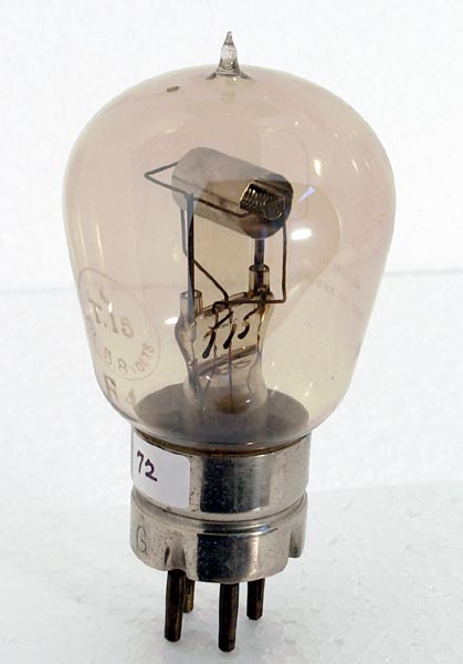 
Like the type R, type T15 is a direct descendent of the famous TM French military hard valve of 1915. The original French type was designed to be used either as a transmitter or as a receiver, according to need. It is possible that its designers had in mind the possibility of one-valve transceivers in which the same valve was used alternately for transmission and reception. Sets of this type are technically possible but are inconvenient to operate because of the adjustments necessary between listening and sending.
Transmission requires more power, and hence greater filament emission, than reception. The Tungsten filaments of French valves were normally operated from a 6 V vehicle battery of the lead-acid type with a rheostat included in the circuit to adjust the voltage applied to the filament. For transmission the filament voltage could be turned up to almost the full available 6 Volts. At this voltage the current drawn was in the region of 0.9 to 1.0 Amp and up to 60 mA of useful emission could be obtained. Filament life was short (a few tens of hours at most) but this did not matter much if transmission was used only occasionally and for short messages. The best French valves could withstand up to 1000 V on their anodes
For reception, the filament rheostat would be turned back to run the filament at around 4 Volts, 0.7 Amp. The available emission was reduced to a few mA but, with care, a life of 1,000 hours was possible. In practice the filaments became brittle when used at high ratings and tended to fail early due to fracture. However, another advantage of using reduced filament voltage for reception was that certain impurities in the filament material tended to make valves electrically 'noisy' when run at maximum brightness.
The disadvantages of the dual-purpose concept became apparent when mass production of the French type was attempted in British lamp factories. Transmitting valves run hotter and require a much better vacuum than receiving valves which will only ever have to withstand low voltages. Transmitting valves therefore need to be run hotter and stressed at higher voltages whilst still on the pumps. Better pumps are needed but even so the whole pumping operation (called processing) takes much longer than for low-power valves.
It soon became clear that, due probably to contamination during assembly, a high percentage of mass- produced valves took 'for ever' to process to the standard necessary for operation at 1,000 V anode rating. Attempts to speed the processing often 'killed' valves whilst still on the pumps, or left them with over-brittle filaments. It was simply not practical, under wartime factory conditions, to insist that every valve should be processed to the full 1,000 V specification.
The solution adopted is clear in general terms but some of the details can only be guessed at. The story set out below includes an element of informed guesswork. We must remember that details of military valve production were covered by the Official Secrets Act so there are no contemporary published accounts.
The first manufacturing change seems to have been a decision that individual valves should be processed only as far as could be achieved easily, and would be marked to show the level of processing thus achieved. Three grades seem to have been authorised: (A) Full processing to 1,000 V suitable for all applications; (B) Satisfactory processing to at least 600 V suitable for many smaller transmitters; (R) Processed to at least 100 V suitable only for receivers. Of these, Grades B and R were the norm; valves graded A were (and are) scarce.
The next stage of change would follow naturally. Since valves were pumped in batches joined to the same pump chain, it was inconvenient to continue processing some of each batch after the rest had reached their limit. Moreover, some production lines in some factories consistently produced a greater proportion of better valves than others. With the demand for all valves still rising, it made sense to separate the A, B and R grades into types rather than grades and to place contracts for each type with those manufacturers who could demonstrate their ability to deliver. This eventually solved the supply problem for types B and R (of which many specimens survive) but Grade A valves were still unreasonably difficult to make in quantity and very short-lived in service.
At the same time there were urgent demands, particularly from the Navy, for much more powerful transmitters. The obvious solution was to abandon the troublesome Grade A and to replace it with a range of altogether more powerful valves made to new designs which took full account of the lessons learned from making and using the French type. Starting around Winter 1916/17, the new range was developed, mainly by Osram (later MOV), under Navy sponsorship and eventually included the T15, the T30, the T50, the T100, the T250 and the T450. Of these, only the T15 retained the French design almost unchanged; The other, more powerful, types (the numeral in the type number indicates power rating) are larger although they still retain the basic Tungsten filament and cylindrical electrode concept.
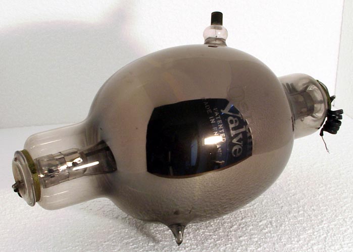
With respect to the shape of the more powerfull early transmitting valves. The type of glass which had to be used for most early transmitting valves tended to become slightly conducting, and also 'lossy', when hot. When a valve oscillates powerfully with a high HT voltage applied, there is a substantial RF electromagnetic field surrounding the electrode structure and penetrating the glass envelope. This induces RF power losses in the glass itself and such losses are increased if the inside of the envelope is blackened by use. In short wave operation these losses increase further and can soften the glass sufficiently for the valve to collapse. Later developments included the use of silica glass, or ceramics, for valve envelopes but in the early days the available solutions were to enlarge the glass envelope so that it was as far as possible from the region of high RF field, and to enforce a generous factor between the permissible 'dead loss' rating with no RF present and the actual dissipation under in-service conditions. The T450 was factory tested dissipating 450W at the anode under 'dead loss' i.e. no RF output, conditions but was rated to dissipate not more than half of this under (brief) key down conditions (less if used on 'short waves') and less still under average keying conditions. Even so, the bulbous envelope, allowing extremely generous spacing of the glass from the electrodes, is the type's most visually obvious feature.
Note, however, that many of these types (or close derivatives) may carry alternative type designations (NT, AT, VT, etc.) according to the Service which used them. Also, there were numerous derivatives for special purposes such as transmitter modulation. For example, Type T15A was a modulator variant of the T15, having a wider grid pitch.
The style of labelling shows that the specimen in the photo above is a late example manufactured in the later 1920s. Note the Type Number hand written in ink on the pinch. This feature is often of value when attempting to identify 'mystery' valves.
|