|
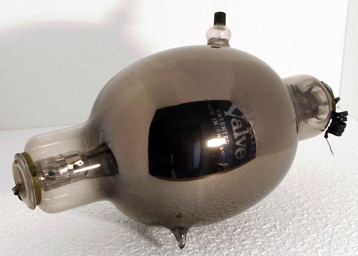
The style of labelling on the T450 shows that this specimen dates from around 1930 although the type dates back to around 1919, at which time it was 'top of the range' in respect of power rating. On the whole M-OV manufactured the 'T' range for Service use, and for export. Valves manufactured for MWTCo. (later The Marconi Company) were usually variants supplied to Marconi specifications and designated with 'MT' type numbers. M-OV would brand its valves as 'M-OV', 'MWTCo', 'Marconi', 'Osram', 'GEC' or 'Marconiphone' etc. according to the market in which the valves were to be sold.The 450 in the designation refers to the nominal rating of the valve in Watts. However, this needs to be interpreted with caution since 'nominal rating' could carry any of several quite different meanings.In the early days it was impractical to measure the RF output power of a transmitter under normal conditions of use. What could be measured was the DC input power (HT volts x mean HT current). This was used to indicate the nominal transmitter power even where, as often, less than half of this was radiated from the aerial in a useful form.Moreover, the mean HT current would depend on the type of modulation in use. Usually, but not always, the nominal power rating referred to steady CW (morse, etc.) transmission with the key temporarily held down, since this was one type of worst-case rating. Note: holding the key down is useless for communication but was necessary from time to time in order to retune the transmitter. Under normal morse conditions (Interrupted CW) the average power input was, of course much less.Another important worst case could occur if, during retuning procedures, the transmitter stopped oscillating under key down conditions. Assuming the valve was being used as a Class C self-oscillator (as was normal in the early days), failure to oscillate meant loss of self-generated negative grid bias so the valve would be left 'full on' across the HT supply in circumstances where the whole of the HT power input was being dissipated at the anode. In practice, this type of worst case occurred quite frequently and could be a killer. The most commonly used solution was to dimension the valve electrodes so that when the maximum rated HT voltage was applied to a non-oscillating valve which had lost its bias, the valve would naturally draw only as much HT power as it could (just) safely dissipate. The permissible 'dead loss' rating was thus another way of defining the nominal dissipation of a transmitting valve.However, there were further considerations. Neither the current drawn under key down conditions whilst retuning, nor that drawn if oscillation and bias ceased, must exceed the rated capacity of the HT supply. A sensible compromise was to design the valve so that, at maximum rated HT, the key down and dead loss inputs were approximately equal, and to dimension the HT supply to provide this input safely, at least for a few minutes. This meant that rating a valve according to permissible key down input power or according to dead loss rating was essentially the same. Moreover, the HT rectifier valve(s) supplying the transmitter would be rated for the key down or dead loss current they could safely supply, rather than in terms of their own internal losses whilst doing so.Under typical conditions of use the anode dissipation in a transmitting valve was very much less than its nominal rating, for two reasons. First, provided the transmitter was oscillating and correctly tuned, at least half of the HT power input should be leaving the valve in the form of wanted RF output. This output power is not, of course, dissipated at the valve anode. Secondly, if the transmitter was operated under normal morse conditions (ICW keyed), the key would, on average, be 'down' for only about half the time. These two factors, taken together, would reduce the average anode loss to around one quarter of the 'nominal' power rating.This was just as well since the type of glass which had to be used for most early transmitting valves tended to become slightly conducting, and also 'lossy', when hot.The T.450 was factory tested dissipating 450 W at the anode under 'dead loss' conditions but was rated to dissipate not more than half of this under (brief) 'key down' conditions (less if used on 'short waves') and less still under average keying conditions. Even so, the bulbous envelope, allowing extremely generous spacing of the glass from the electrodes, is the type's most visually obvious feature.In practice, then, the actual radiated RF output of this splendid 'top-of-the-range' exhibit was roughly comparable with that of a WWII Type 807.The balloon envelope is 152 mm in diameter and the overall length of the valve is 317 mm.References: Private communication. Type T450 was first introduced in 1919. See also 1919 adverts. |
Updated December05, 2012.
|
|