|
Known devices are CV143, CV144, CV147, CV148 and IR Cell.
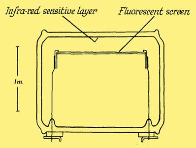
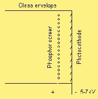
These devices, manufactured by EMI, are high-vacuum image converters. At one end of the device is a semi-transparent silver - oxygen - caesium film facing a cathodo-luminescent screen of zinc orthosilicate having a manganese activator which emits light in the green part of the spectrum.
The phosphor screen is held in a metal ring so that it is approximately 3 mm from, and parallel to, the photocathode.
An electrical connection is made to the photocathode by means of a thin metal ribbon which is sealed through the glass. One of the wires that holds the support ring of the phosphor screen is lead out as its connection.
The devices work with approximately 5 to 7 kV HT. These cells only have a resolution of a few line pairs/mm.
The finished tubes were sealed off with a vacuum of around 10-6 mm/Hg.
It was important not to expose the tube to light above that in which a normally dark adapted eye can see in a dimly lit room.
There is currently no information on the differences between the CV14x range so it is likely there were slight modifications carried out and that each one required a new CV number.
The tube had to be almost 2 inches long so that the phosphor screen could be protected from reaction with caesium during the formation of the photocathode. When a tube was first assembled, the screen plate was held in its support ring close to the cathode window.
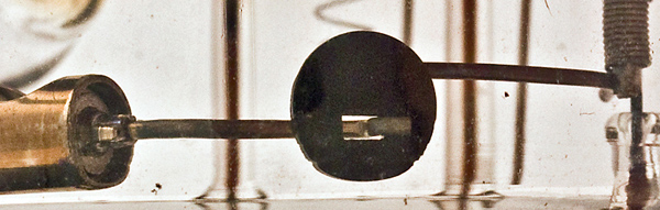
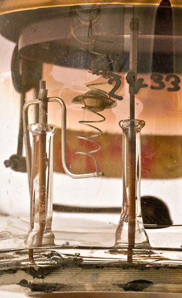
The latch disc holding the silver source in place
Immediately before the tube was pumped down a hand-held magnet was used to pull out the spring-loaded retaining pin holding the screen plate in place. The screen then fell onto the end window and was flipped over by the operator (in an action rather like flipping a pancake) to get the screen side against the window. After this the tube was sealed to the vacuum pump. The magnet was then used to unlatch the silver source and move it into the middle of the tube.
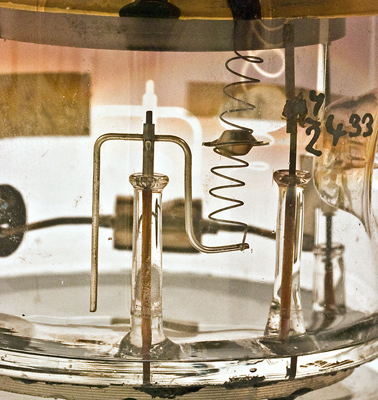
The cylinder on the left held the silver, the black disk is the support latch and the foreground shows the springs
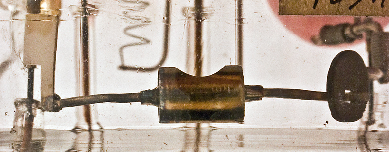
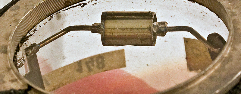
The cylinder holding the silver source
The magnet was held in place to hold the swinging end of the silver source support against a wire connection, and a current was passed through to activate the source, depositing an even layer of silver on the cathode window to the correct thickness. After this the magnet was used to return and lock the silver source out of the way.
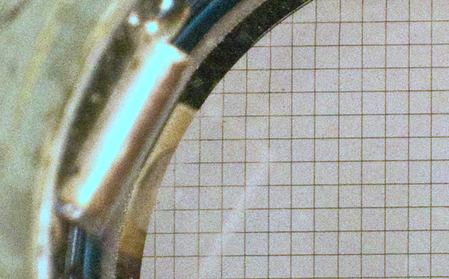
The silver source seen through the viewing window
After this a vacuum valve disconnected the tube from the pump, a small pressure of oxygen was introduced and a glow discharge started in the tube. This was stopped when the correct amount of oxide had formed, and the excess oxygen was pumped out. The caesium source was then slowly activated to allow the silver-oxide to acquire photosensitivity. A small lamp was used to excite the photosensitive cathode, the progress of activation being measured by a microammeter and small battery connected across the tube. The end point was determined by a falling off of the photo current, at which event the reaction was stopped and the tube then sealed off.
A quick flip of the operator's wrist got the phosphor screen back into its correct position with the screen facing the photocathode again. The magnetic catch was then operated to hold the screen in place.
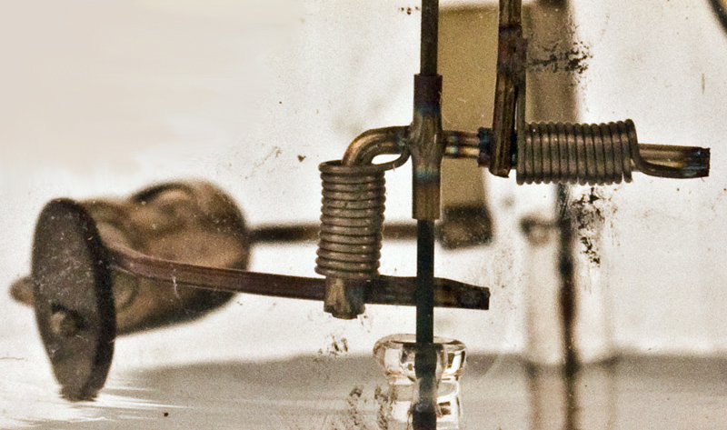
Insulated supports and the screen tray at the top
Tubes were then tested in total darkness to locate any unwanted bright spots due to field emission from dust particles left on the cathode. These were eliminated by projecting a focused arc lamp onto the cathode at the offending place. This burned a hole in the cathode and resulted in a black spot in the final image.
Platinium mesh to allow an equi-potential screen
The grid structure that can be seen in some of the exhibits was a film of platinum created by vapourisation through a mask. This made connection with the phosphor and stabilised the potential over the whole screen area. There were other schemes employed too, such as continuous semi-transparent metal films, and aluminium coatings.
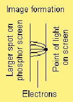
In operation light falling on the photocathode causes electrons to be emitted with a voltage of between 0 and 5 electron Volts. As these do not all travel in an exactly straight path the spot on the phosphor screen will always be bigger than the spot on the photocathode.
The screen at the top and insulated support below
At the operating voltage of 5 to 7 kV, the 3 mm separation between the photocathode and phosphor screen is the minimum below which arcing might occur.
The original power supplies used Zamboni Piles as their power source. They were invented in 1812 and consist of stacks of many disks of zinc and carbon coated paper, moistened with ammonium chloride and housed in a sealed plastic tube. The device draws only a few microamps and so these batteries had a long life; in practice they were made non-replaceable. (see also here)
A paper published in 1947 detailing the CV14x range can be found here.
Original information kindly provided by F John Marshall (fjohn.marshall 'at' att.net) who used to work on these devices while at EMI.
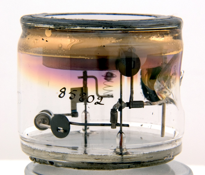
Complete IR night vision tube
|