|
Introduction of specialised types of multiple valves will help set makers to cut size and cost of their products. Engineers should keep abreast with these developments to be ready for the advanced circuits appearing in new models.
Multiple valves are commonplace and over the years more and more electrodes and complete valve sections have been assembled in a common envelope. From early experience, it was thought that this process was bad for the user owing to his being obliged to purchase, in effect, replacements for still healthy parts should just one section of a multiple unit fail.
While there is the possibility of just one section of a multiple valve failing, leaving the remaining section or sections in good condition, this is not a frequent occurrence. Sometimes there are common electrodes, like the heater and cathode systems of some double triodes and triode pentodes. Wear in one section often signifies that the other sections are equally as worn.
With the growing complexity of TV receivers, together with simultaneous advances in the design of electrode systems for specific purposes, valve manufacturers have turned attention to the development of multiple valves having completely independent electrode systems.
A valve of this kind is the PFL200 introduced recently by Philips. This is a double-pentode, and the first valve of its type ever to be made. To take the electrode connections of two pentodes, a new 10 pin base has been evolved, called a Decal (B10B) base. The bulb diameter of the valve, however, is identical with that of valves using the conventional 9-pin Noval (B9A) base.
One -section of the PFL200 is a power pentode designed with video amplification in view. It is of frame grid construction and can handle high peak anode currents without distress. The other section is a smaller type of pentode suitable for use as a keyed and/or noise-gated AGC amplifier, as a sync pulse separator or as an amplifier for the inter-carrier signal in 625 line sets.
Negative Going
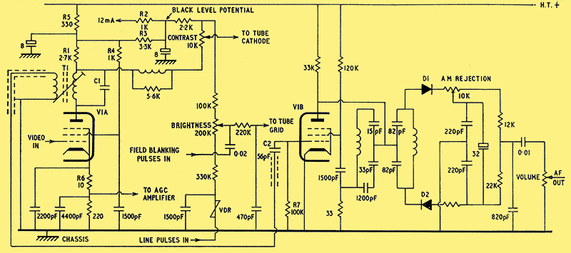
Complete circuit diagram for video amplifier, inter-carrier sound amplifier, FM limiter, gain and brightness control stages built round a single Philips PLF200 decal-based double-pentode valve.
A circuit which has every possibility of being adopted in British receivers when the PFL200 is generally available in the UK is shown above. Here the power pentode section V1A is arranged as the video amplifier and the smaller pentode V1B as the inter-carrier amplifier.
Picture signal is applied to the control grid of V1A from the vision detector. Note that the circuit in this section is concerned with the negative-going vision signal of the 625-line standard. Dual-standard switching would be adopted in the conventional way to cater for the 405-line standard. The valve works normally with R1 as the anode load, across which the video signal is developed.
The anode of V1A is also loaded with the primary winding of the inter-carrier transformer T1. C1 tunes the transformer to 6 MHz (the British inter-carrier frequency, which is the frequency difference between the sound and vision carriers) and the resulting inter-carrier signal is induced into the secondary winding and fed through a low impedance loop to the inter-carrier amplifier valve, V1B, which will be considered a little later.
There are two initial considerations regarding the video anode circuit. One is the low value anode load R1 and the other is the potentiometer contrast control network. To secure adequate video drive for the picture tube, most conventional video amplifiers use anode loads up to about 10 kΩ in value. However, due to the effect of valve and stray capacitances, good response at the higher video frequencies (to provide good picture definition) is possible only when using a low value anode load (and, also, incidentally, vision detector load). As a 625-line signal has a wider extension into the high video frequencies than a 405 signal, the problem is greater in the new sets.
To ensure a good video response, the shunt capacitances must be small and the resistive load value must also be small. But as the load is decreased, so does the amplitude of the video signal across the load fall off. As a picture tube requires a certain value of video drive for peak white there is a limit, for a particular value, beyond which the value of the load cannot be reduced.
Factors in Favour
The problem is further aggravated in the circuit shown because the contrast control is connected in the video anode circuit and this itself, together with its wiring, introduces extra shunt capacitance. On 625 lines, a response beyond 6 MHz is needed for both picture quality and the inter-carrier signal, so only a low anode load resistor can be used. It is seen that the value is 2K7.
Sufficient video signal drive is provided, even with this low load, because: (a) the slope of the power pentode section of the PFL200 is high and (b) the valve is designed for the high peaks of current which must occur in the load at maximum drive.
It may be thought that the problem is made more complicated than need be by having the contrast control in the anode circuit. Actually, there are several. factors in favour of this mode of contrast control. A significant one is that the level of the video signal at the sync separator and the level of the inter-carrier signal at the vision detector both remain constant despite manual adjustment of contrast.
The vision AGC also ensures that the levels of these signals are held constant during changes of input signal as may result from fading and channel changing. constancy of signal level at these points provides stable synchronising reasonably inexpensively and without complex clippers and ensures constant AM limiting in the FM sound circuits.
The black level potential is obtained by R2 being connected to a circuit which requires a current of 12 mA. The final IF stage can be used to draw this current. The 12 mA is driven through R3 from the upper end of R1 and about 40 V develops across R3, this being equal to the black level potential.
Now, under black level conditions there is zero voltage drop across the contrast control, so modification of its setting will not entail any variation of the black level and background brightness.
The arrangement also keeps the voltage across the contrast control down to about 50 V even under zero signal conditions which means that an ordinary carbon 1 W control can be used.
The contrast control network also provides for de-emphasis of the DC gain of the video stage which, due to the relatively high series impedance of the power supply circuits, out weighs the AC gain. Suitable correction is given by the components already considered and by the voltage-dependent resistor in the earthy side of the brightness control. Correction occurs over the range of the contrast control.
In the absence of a signal, the bias of the video amplifier section as normally provided by the signal itself is removed and the valve runs into peak anode current. To avoid trouble in this respect, the current is limited by the screen grid resistor R4 and the common HT feed resistor R5.
Grid current during transmission of peak white signal (which, remember, on 625 lines represents only about 10% carrier) is avoided by the 10 Ω resistor R6 in the cathode circuit. This gives about 0.7 V bias and the signal itself provides an effective 0.3V.
Lingering Spot
Note that the signal developed across the 220 Ω cathode section feeds, in some receivers, the AGC amplifier in a reasonably conventional manner.
The VDR in the brightness circuit also provides a quick close-down of tube beam current when the set is switched off to avoid the lingering spot effect. In this application (which is not new) the VDR acts as a diode and rectifies the line pulses applied to it, thereby producing a negative voltage at its top end. This potential is applied to the lower end of the brightness control network.
At switch off the negative potential drops and the tube grid is effectively increased positively. In addition, the VDR impedance increases and this drives the tube grid further positive. The combined effect is that the beam current rises to a high value while the scan is collapsing and the EHT charge, which could cause the spot to linger, is swiftly dissipated.
Since section V1A of the valve steps up the inter-carrier signal as well as the video signal, the signal applied to V1B section is of high level. This is useful, for it means (a) that only a little extra amplification is required and (b) that the inter-carrier amplifier can be arranged as a limiter to prevent undue amplitude interference effects and inter-carrier buzz trouble.
All that is required for inter-carrier signal amplification is. in fact, V1B section of the valve. The limiting action is provided in the conventional way by the leaky grid arrangement comprising the charging capacitor C2 and the resistor R7.
The circuit issued by Philips has a ratio detector of a type which does not call for a special transformer. D1 and D2 are the ratio detector diodes and the circuit is carefully balanced ultimately by the AM rejection preset for minimum response to AM signals.
We thus have a complete video amplifier, gain and brightness control stage and inter-carrier stage all based on a single valve envelope.
More on the Way
Another new valve is one in the Mazda range (Thorn-AEI Radio Valves and Tubes). The 30FL14 combines in one envelope a high-slope frame grid VHF straight characteristic pentode and a general purpose separate cathode triode. A suggested use is with the pentode as an IF amplifier and the triode as a scanning oscillator.
A new triode-pentode from Mullard is the PCF802. For this a suggested application has the pentode section acting as a sine-wave oscillator for the line timebase and the triode as a reactance valve across the oscillator to control its frequency. Control is by a correction voltage produced by a discriminator which picks up a sample of the line signal as well as the line sync pulses.
This is based on the normal flywheel line sync technique, of course, where the line oscillator is brought back into frequency should the frequency wander from that of the sync pulses. The adoption of negative vision modulation for 625 lines makes a flywheel controlled line oscillator almost a necessity
A further triode-pentode is the PCF801. The valve is designed so that the two sections can work as an oscillator/mixer in the normal way in VHF tuners and the pentode alone as an IF amplifier following a UHF tuner, as in current dual standard models.
Frame grid construction is used on the control grid of the pentode and the grid of the triode. Large signals from a UHF tuner can be handled by the pentode without risk of cross- modulation or over-modulation taking place; The two sections have high stability when working as a VHF oscillator/mixer.
Also found in the new dual standard models is the heptode EH90 in a locked-oscillator FM discriminator circuit (see Locked Oscillator FM Detector), the PL500 line output pentode, which possesses an exceptionally high ratio of anode current to screen-grid current as well as improved ratings, and the PY88, booster diode, also with improved current and voltage ratings, as demanded for efficient working of the new dual standard models.
|