|

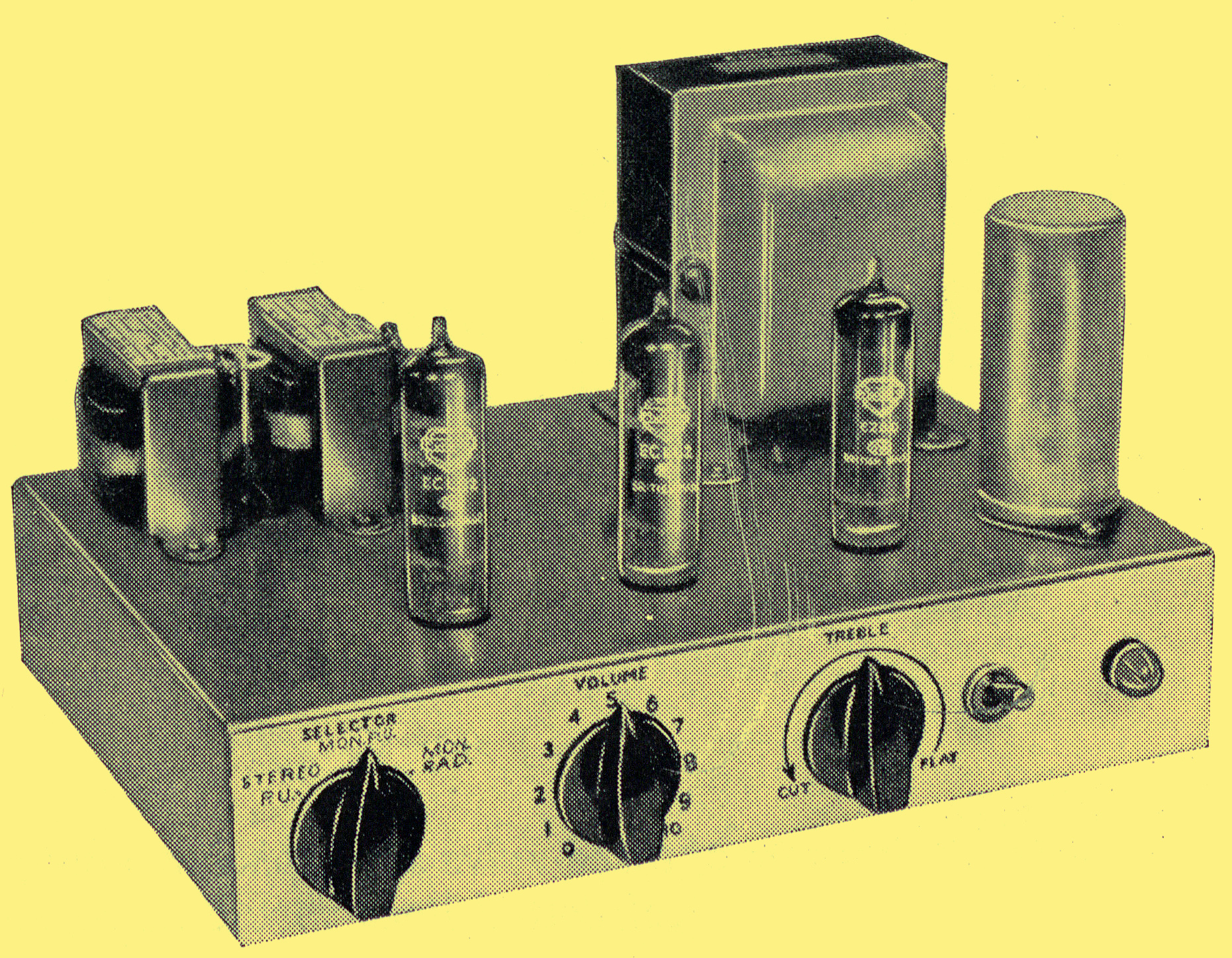
Prototype of Three-valve Stereophonic amplifier.
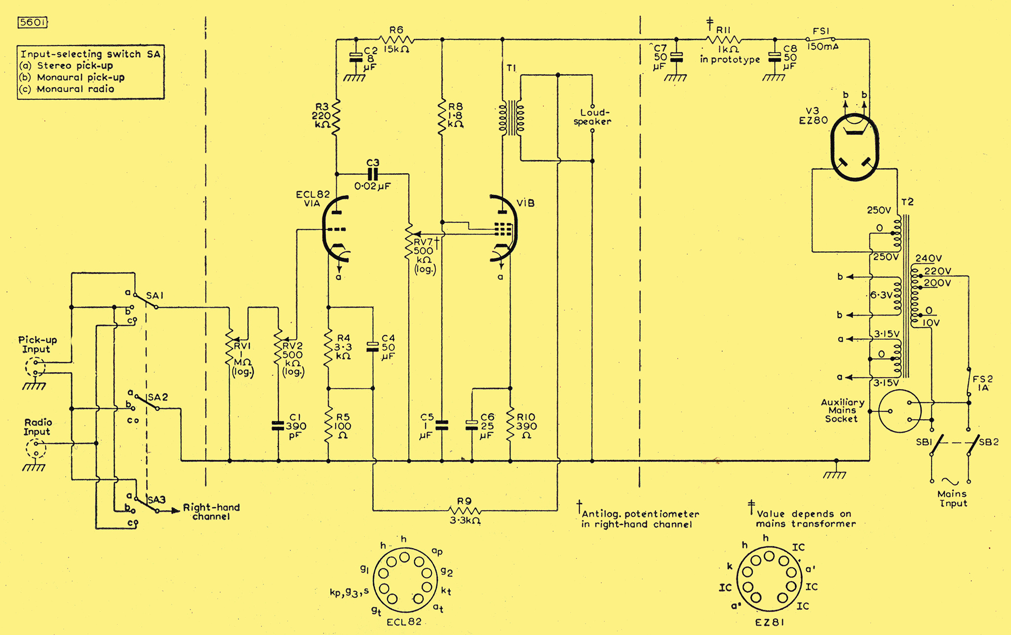
The circuit drawn in Fig. 1 has been designed to provide dual-channel stereophonic amplification of a reasonably good quality at a fairly low cost. Only one channel of the amplifier is shown in Fig. 1. The circuitry appearing between the dotted lines is for the left-hand channel only: it should be duplicated for the right-hand channel. The circuitry drawn outside the dotted lines (the power supply, for example) is common to both channels. Each channel uses one Mullard triode pentode, type ECL82, the triode section of which is used for voltage amplification and the pentode section for power amplification. The HT supply for both channels is obtained from one Mullard full-wave rectifier, type EZ80.
The input sensitivity of each channel for the rated output of 2 W is 280 mV, which is adequate for use with the majority of stereophonic crystal pick-up heads. This sensitivity has been achieved in spite of the small complement of valves by using only a small amount (approximately 6 dB) of feedback in each channel. The distortion occurring when a continuous sine-wave signal is applied to the input is about 5%, but under the normal input conditions of speech or music signals, the level of distortion will be somewhat lower. The amplifier, although not comparable in specification with high-quality equipment, has been found to give most pleasing stereophonic results during listening tests in normal-sized living rooms. The feedback voltage is taken from the secondary winding of the output transformer of each channel and injected in the cathode circuit of the triode section of the ECL82 in that channel.
Circuit Description
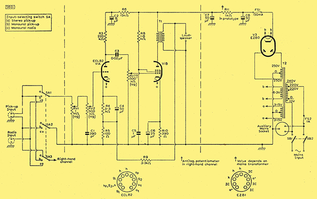
Fig. 1 - Circuit diagram of three-valve stereophonic amplifier (left-hand channel only is shown: circuitry between vertical dotted lines should be repeated in the right-hand channel).
Resistors and capacitors appearing in the left-hand channel of the amplifier are numbered 1, 2, 3, etc.; the corresponding components in the right-hand channel are numbered 101,102, 103, etc.
Input Selector Switch.
The input stages of both channels are connected to the 3-way selector switch SA. The switch positions indicated in Fig. 1 provide the following facilities:
- Stereophonic reproduction from stereophonic crystal pick-up heads.
- Dual-channel monaural reproduction from a monaural pick-up head. In this position, the left-hand pick-up input terminal is 'live', and both channels are connected in parallel at the input. The input terminal for the right-hand channel of a stereo-phonic pick-up head is earthed at position b of SA2. If position b of SA3 is earthed instead of being connected to position b of SA1, single-channel reproduction is possible.
- Dual-channel monaural reproduction from an FM tuner unit. The input socket in Fig. 1 is connected for monaural applications. If position c of SA3 is connected to the right-hand input terminal instead of the left-hand terminal, the circuit will be suitable for reproducing stereo-phonic transmissions. If position c of SA3 is earthed instead of being connected to the input socket, the system gives single-channel monaural reproduction from an FM tuner unit.
Input Stage
The triode section of one ECL82 is used in the first stage of each channel for voltage amplification, providing a stage gain of about 50 times. A volume control RV1 (RV101) is included in the grid circuit of the triode section. A simple tone-control network, consisting of the components RV2 and C1 (RV102 and C101) is also incorporated in this grid circuit. The control provides continuously variable treble cut and, with full application of RV2 (RV1O2), gives at least 20 dB cut at 10 kHz. Dual-ganged potentiometers are used in the prototype for the volume control components RV1 and RV101 and also for the tone-control components RV2 and RV102 so that equal adjustments can be made simultaneously to both channels. It may be found more convenient to use dual concentric potentiometers for the volume and tone controls because these also allow separate adjustments to be made to the channels.
Output Stage.
The output stage of each channel consists of the pentode section of an ECL82. Unless precautions are taken, the acoustical outputs from the loudspeakers of the two channels will not be exactly the same. In order that allowance can be made for any differences, a dual-ganged balance control (RV7 and RV107) is included in the grid circuits of the pentode sections of the ECL82s. This control is made up of a logarithmic-law potentiometer connected in reverse in one channel and an anti-logarithmic-law potentiometer connected normally in the other channel. The characteristics of this type of control are discussed here. If dual-concentric potentiometers are used for the volume control RV1, RV101, balance between the channels can be achieved with them, and the potentiometers RV7, RV107 can be replaced by fixed resistors (470 kΩ).
Power Supply
A conventional power supply using the Mullard full-wave rectifier, type EZ8O, with resistance-capacitance smoothing provides the HT for both channels. The supplies are taken from the junction of the smoothing components C7 and R11, these components and the reservoir capacitor C8 being common to both channels. The total HT current drain of the amplifier is 86 mA at 220 V and the total heater current is 2.56 A at 6.3 V.
Construction and Assembly
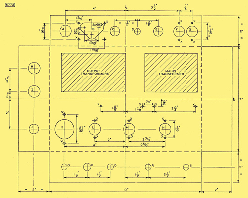
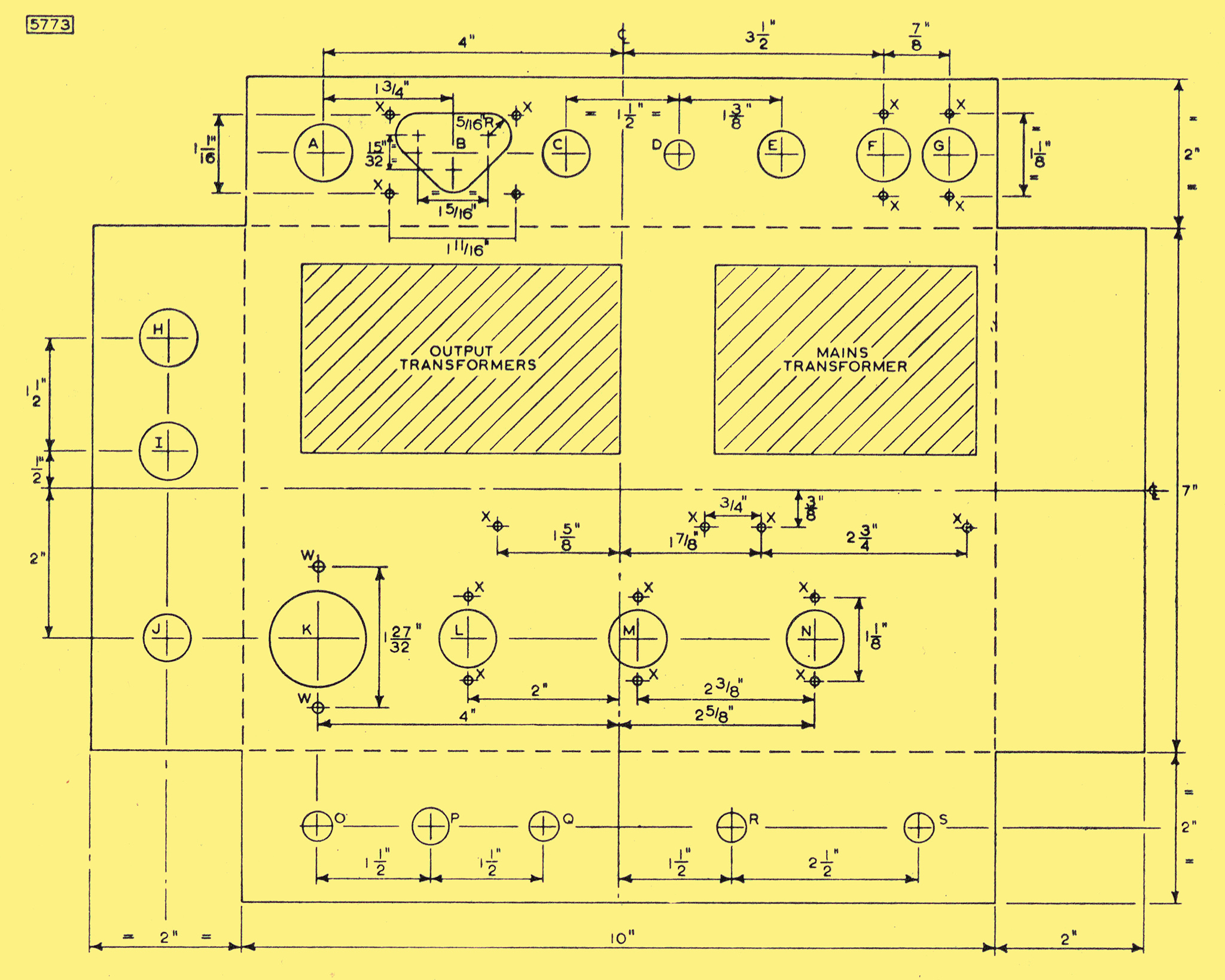
Fig. 2 - Chassis details (chassis should be bent up at 90° at all dotted lines).
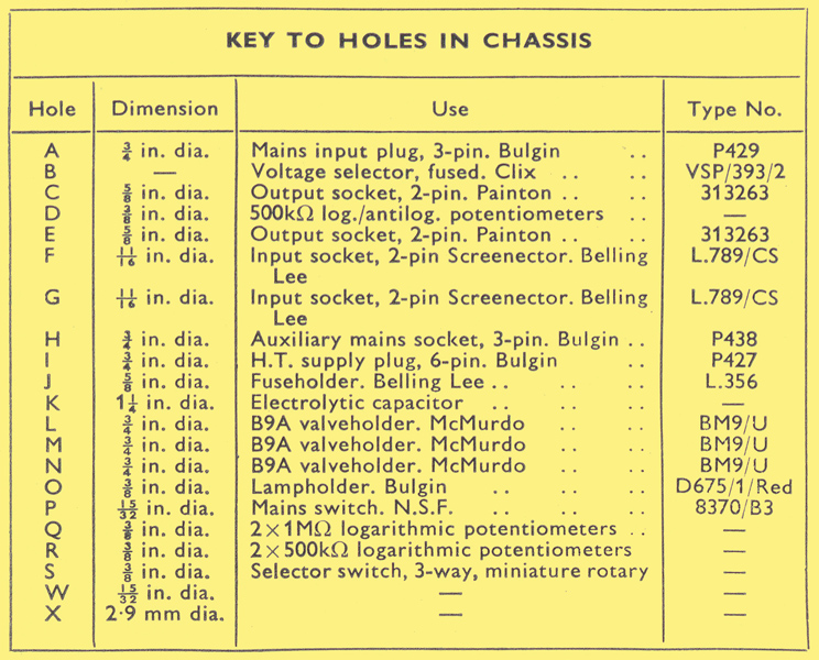
Chassis hole dimensions.
The chassis for the 2 W stereophonic amplifier is made from one piece of 16 SWG aluminium sheet 14 in. long and 11 in. wide. This piece should be marked as shown in the drawings of Fig. 2, and the holes should be cut as indicated.
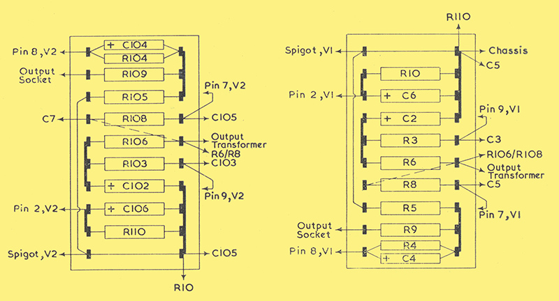
Fig. 4 - (left) Tag-board No.1 (components of right-hand channel).
Fig. 5 - (right) Tag-board No. 2 (components of left-hand channel).
Most of the smaller components are mounted on two tag-boards. The components for the right-hand channel are arranged on Tag-board No. 1, and those for the left-hand channel are mounted on Tag-board No. 2. Details of these boards are given in Figs. 4 and 5 respectively. It will be observed that the arrangement of the components on one board is the 'mirror-image' of the arrangement on the other.
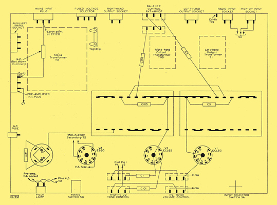
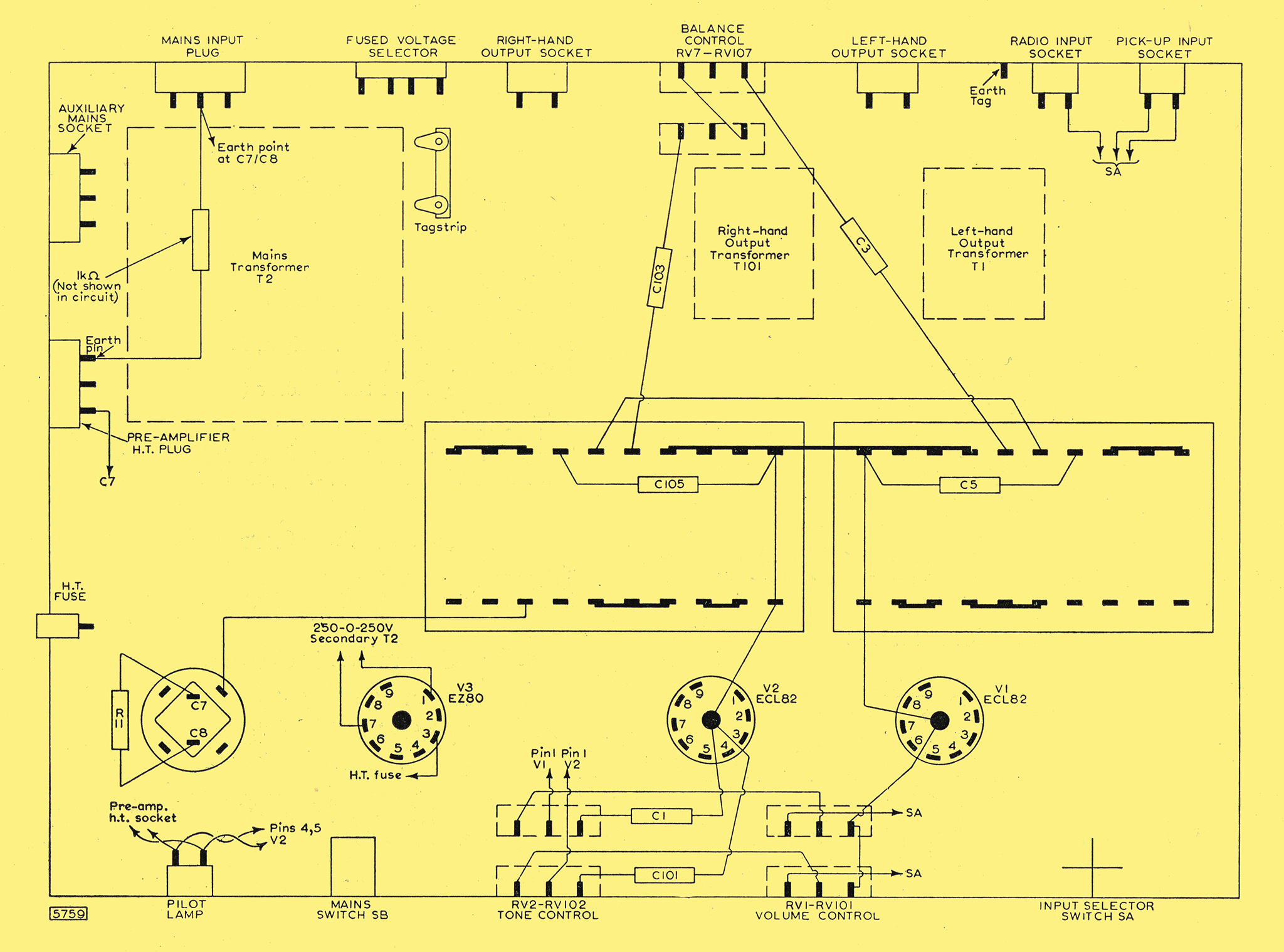
Fig. 3 - Suggested layout of components.
The larger components such as switches, valve-holders and transformers should be mounted on the chassis in the position indicated in the layout diagram of Fig. 3. The recommended wiring between these components is also shown in Fig. 3. The wires connecting the input sockets to the selector switch should be taken along the edge of the chassis beneath Tag-board No. 2. This arrangement follows the practice normally adopted in audio equipment of separating by as much as possible the sensitive input circuit from the rest of the amplifier.
Performance
Distortion
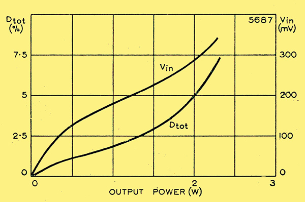
Fig. 6 - Variations of harmonic distortion, Dot and input voltage Vin with output power.
The total harmonic distortion was measured in the prototype amplifier with a continuous sine-wave input signal at 400 Hz. With 6 dB of negative feedback the distortion for the rated output of 2 W per channel is approximately 5%. The level of distortion for speech or music input signals is somewhat lower than this. The variation of distortion with output power is plotted in Fig. 6.
Frequency Response
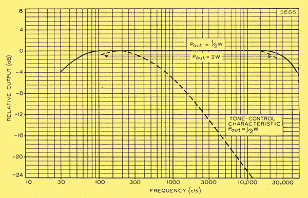
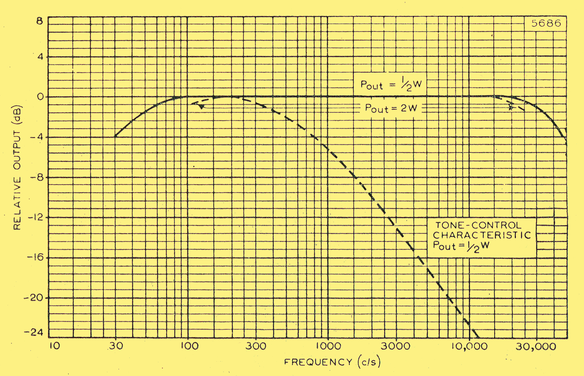
Fig. 7 - Frequency-response, power-response and tone control characteristics.
The frequency-response characteristic of each channel of the prototype amplifier is shown in Fig. 7. This response is 3 dB below the response level at 1 kHz at frequencies of 40 Hz and 40 kHz.
Tone Control
The tone-control characteristic is given in Fig. 7. From this it can be seen that 23 dB of treble cut are available at 10 kHz with full application of the control.
Sensitivity
The sensitivity of each channel of the circuit with 6 dB of negative feedback is 280 mV for the rated output of 2 W.
Hum and Noise
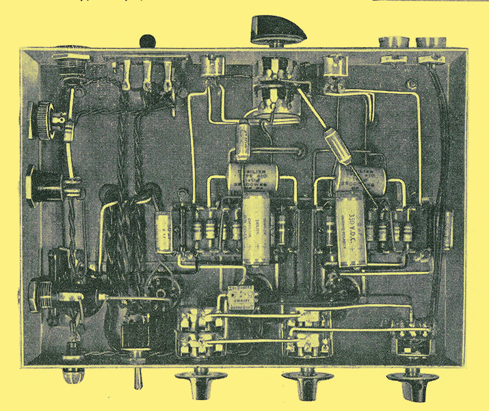
Underside View of Prototype Amplifier.
The level of hum and noise in each channel of the prototype amplifier is at least 62 dB below the rated output.
DC Conditions
The DC voltages in each channel should be tested with reference to Table 1. The results shown in this table were obtained with an Avometer No. 8.
Table 1.
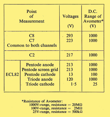
DC conditions in each channel.
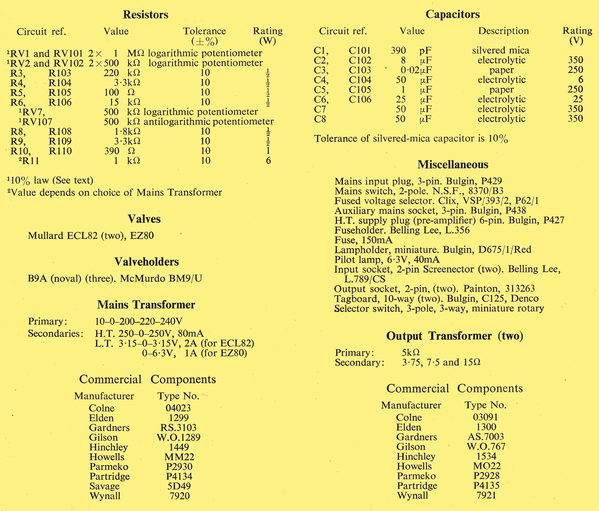
List of Components.
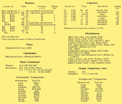
Resistors and capacitors in the left-hand channel are numbered 1, 2, 3, etc.; corresponding components in the right-hand channel are numbered 101, 102, 103, etc.
|