|
This is edition two published in 1962 by Mullard 1045
Introduction
I was given this book as a schoolboy aged 14. It was the woodwork prize awarded in July 1964 and the prize label is still inside. The following year I constructed a walnut fronted cabinet to house the 5-10 amplifier. The amplifier was never constructed and the cabinet still sits under my father's bench in his garage. I doubt that the solid walnut front looks pristine after 44 years as a drawer base.
The book has been read and re-read many times over the years, I will now share with you a few selected chapters that are of interest today (2008). As a matter of health and safety I will not re-publish the designs for universal or AC/DC or mains transformer-less amplifiers. If connected up incorrectly the chassis is at mains line potential and so is any associated equipment. Death awaits! As a twelve year old in the garage with my father as he build a new set of kitchen cabinets. We are talking 0.5 inch blockboard, hot applied animal glue and proper joints. I had a small bench on which I hooked up external speakers to my grandmother's old radio using cheap toggle switches. These were intended for battery circuits and the metal toggle was also the active switching element. Like a good boy I was wearing rubber soled shoes and also I remembered what my radar mechanic uncle had told me that you always work on live equipment with one hand behind your back. This saved my life I think. As I touched the switch to turn on my second speaker I felt a pronounced tingle up my right arm. I pulled my arm away and stopped to think things through. OH - LIVE MAINS. That radio ceased to be a source of experimentation.
As an aside, that summer of '62 on Sunday afternoons in the garage is memorable for the smell of the glue, Frank Ifield at number one for 13 weeks with I Remember You and the Light Program with its Sing Something Simple offering. With hindsight this summer was the end of an era, the following year the Beatles and being 13 made staying in the shed as a short wave listener and building my own one valve receiver (Radio Luxembourg on 208 Metres and Horace Bachelor's adverts for his Infradraw method of winning the pools together with Keynsham - that's K E Y N S H A M Bristol) much more exciting.
Back to Mullard.
These amplifiers were the product of their applications lab and the first design was the Mullard 5-10 from 1954. These started out as being published in their technical bulletins and were later collected into book form. I also have the ECL86 pamphlet4094 from 1962 and the ECL86 designs are taken from this. The first article is High Quality Amplification that describes the design process. This is followed by the stereophonic pre-amplifier, the Twenty Watt amplifier, the 5-10 ten Watt amplifier, the 10 ten Watt stereophonic amplifier, the economical three Watt stereophonic amplifier, three-valve Stereophonic Amplifier and finally the 3-3 three Watt amplifier.
Included here is the contents of the chapter on construction and assembly. This should be read whilst remembering that the domestic environment of the mid 1950s was very different to the early part of the 21st century. Today there are many more sources of electronic noise in the home and it would be sensible to include in the mains input circuit an encapsulated mains filter unit. Also little reference is made to the use of screen cable in the high impedance low signal level parts of the circuit, current practice would be to use such a cable.
General notes on construction and assembly
Details are given in the amplifier designs of the dimensions, layout and wiring of each item of equipment. This information is extensive, but no claim is made that it is exhaustive. The constructional sections of each design should be regarded principally as giving some guidance for assembling the equipment, but should not be considered to be absolutely inviolate sets of rules and instructions. An intelligent use of these sections, coupled with references to circuit diagrams, should produce excellent results.
The suggested arrangements of components in the various chassis are those adopted in the prototype equipment. The convenience of the constructor has been borne in mind in evolving these layouts, and economy of space has been effected whenever possible. However, the underlying principle has always been to obtain the best possible standard of performance for a given expenditure. A good margin of stability, a low level of hum, and so on, have never been sacrificed in an attempt to achieve attractive, but less fundamental, properties such as miniaturisation.
There is no theoretical method of deducing the best layout for audio equipment. It has to be found experimentally, and it follows that the effect of any deviations from an established arrangement cannot be predicted. Consequently, any alterations to layouts recommended should not be undertaken lightly. They should be dictated by strong reasons, and the subsequent variations in performance should be analysed closely.
Similarly, recommendations for good-quality valve-holders and for high-stability resistors, for example, are based on experimental proof of their necessity. Any change from the recommendations can alter the performance considerably. The voltage ratings quoted for capacitors, however, should be regarded as minimum values and capacitors with higher ratings may be used if so desired. In these respects, the home constructor is advised to choose his components very carefully, and complete sets of components or constructional kits purporting to be used with specific Mullard circuits should be examined closely. Mullard Limited only design and publish the circuits: they have no control of material and components sold for use with their circuits. (modern i.e. 2008 capacitors are much better than the post war devices, advances in materials science etc. have seen to that)
Small Components
Mounting of components on tag-boards.
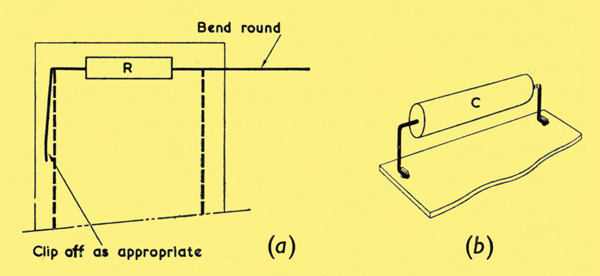
The smaller components are normally mounted on tag-boards, and it is generally more convenient to solder them to the tags before the boards are mounted in the chassis. The small carbon resistors should be laid across two tags and the lead wires bent around the tags in the manner shown in (a) above. If the tag-board wiring diagrams show that neighbouring tags should be connected together, the lead wires of the appropriate components should be cut to lengths sufficient to allow this. Waxed capacitors, silvered-mica capacitors and high-stability resistors will require longer leads so that they will not be over-heated when soldered into position. The leads should be bent as shown in (b) above, care being taken in doing so to avoid making sharp bends very close to the ends of the components.
Components such as the germanium diodes which are particularly sensitive to temperature, will also require long lead wires. These wires should also be held with a pair of pliers. to act as a heat shunt when soldering. The polarity of Mullard germanium diodes is decided by the outer markings: usually the negative pole is the end on which a band is marked.
Earth Connections
In audio equipment, it is advisable to have only one direct connection to the chassis, and this should be made close to the input socket. With a number of connections, eddy currents can be set up in the chassis and hum voltages can be induced in the sensitive sections of the equipment by the magnetic fields associated with these currents. Normally, a common earth lead or busbar is recommended, and the centre spigots of the valve-holders often serve as convenient points for securing this lead.
To maintain a low level of hum when two or more units are used together, the chassis of the units should be connected by one lead only. If the negative return line is conveyed from one unit to the other by way of the power cable, the connection between chassis should not be duplicated in the AF coaxial lead, and one end only of the outer conductor of this lead should be earthed.
Whenever possible, an external connection should be made from the equipment to earth. This lessens hum pick-up and may also help in eliminating any undesirable RF signals that can occur in equipment situated near radio or television transmitting stations.
Output Transformers
The quality of the output transformer will govern to a great extent the quality of the output from the loudspeaker. A poor component can give rise to a high level of distortion and can cause instability. The most important factors determining the performance of an output transformer are:–
- Primary-winding inductance
- Leakage inductance
- Core material and core size
- Intrinsic capacitance of the coils (especially of the primary)
- Capacitances between the various coils
- Power efficiency.
In an actual design, a compromise has to be found between the inductance and capacitance of the primary winding. The inductance must be high enough to minimise the fall in response which occurs at low frequencies. On the other hand, a high inductance necessarily produces a high self-capacitance because of the large number of turns required, and this can result in a large loss in voltage at high frequencies.
The inductance and self-capacitance of the primary winding form a parallel tuned circuit in the output stage, and the resonant frequency of this must be as high as possible. It is usually between 50 and 100 kHZ in a good transformer. Furthermore, the capacitance must be low to prevent an increase in the phase shift when feedback is used. A high capacitance can give rise to low-frequency instability in the amplifier. The capacitance can be minimised by careful winding of the primary coil.
If the coupling between the primary and secondary windings of the transformer is not close enough (corresponding to increased leakage inductance) excessive phase shift will be introduced at high frequencies which may lead to parasitic oscillations. Close coupling is often obtained by dividing the primary winding into sections and winding the secondary turns between these sections.
It is advisable to obtain output transformers from manufacturers who build the components for specific circuits. The commercial type numbers listed with the circuits have been supplied by the manufacturers, and the transformers should all prove to be satisfactory in the appropriate equipment.
Negative Feedback
Negative feedback is usually taken from the output transformer to the input stage of a power amplifier to reduce the harmonic distortion in the output signal. The correct polarity of this feedback is essential. Connection to the wrong side of the secondary winding of the output transformer will give positive feedback and will result in oscillation.
The correct connection can best be found by trial and error, and it is advisable to use a low-grade speaker while doing this. With unsuitable phasing (positive feedback) the resultant violent oscillation might damage a delicate speaker-coil suspension. If a low-grade speaker is not available, a momentary completion of the feedback loop should be sufficient to determine the correct phasing.
Should it be desired to experiment with the level of feedback –if RF instability occurs, for example– this can be done by altering the value of the resistor in the feedback loop. If the resistance is increased, there is a decrease in the level of feedback. (A corresponding value of shunt capacitance in the feedback loop must be found empirically.) Except in the unlikely event of RF instability, little advantage will be gained from changing the values of components recommended in later chapters. Audible improvement is indiscernible when the level of feedback is increased above that indicated for each amplifier.
Stereophonic Balance Controls
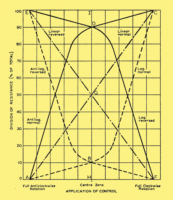
The balance control in stereophonic equipment will often consist of dual-ganged potentiometers connected in the grid circuits of corresponding valves in each channel. One of the potentiometers will be connected normally with its r minimum-resistance end earthed and the other will be connected in reverse, with its maximum-resistance end earthed. The ganged potentiometers could be either a pair of linear-law potentiometers or one logarithmic-law and one anti-logarithmic-law potentiometer. The characteristics of these components, connected normally and in reverse, are shown.
Potentiometer characteristics
The lines AGC and EGF are the characteristics of normally and inversely connected linear potentiometers respectively. If these are used for the balance control, then the need for the centre-zero arrangement will give an operating point at the intersection G of the two characteristics. The resistance corresponding to IG will appear in series with each grid, and that represented by GH will be between the grid and earth. The signal attenuation caused in each channel by this arrangement will thus be 50%.
The curves EDF and ADC are respectively the characteristics of a logarithmic potentiometer connected in reverse and an anti-logarithmic potentiometer connected normally. The operating point with this combination would be the intersection D, and the signal attenuation in the zero position of the control would be only ID/IH. For potentiometers obeying a 10% logarithmic law, the attenuation would thus only be 10%.
Power Supplies
HT and LT current and Voltage Requirements
|
HT |
LT |
Circuit |
(V) |
(mA) |
(V) |
(A) |
20 Watt |
415 |
145 |
6.3; 5.0 |
3.5; 1.9 |
20 Watt |
320 |
80 |
6.3; 6.3 |
2.0; 1.0 |
10 Watt (low loading) |
320 |
60 |
6.3; 6.3 |
2.0; 1.0 |
3 Watt |
310 |
50 |
6.3; 6.3 |
0.96; 0.6 |
Allowance has been made in the circuits of subsequent chapters for adequate HT power supplies. The requirements of each item of equipment dictate the type of rectifier to be used and the specification for the mains transformer.
Limiting resistors for Mullard rectifiers
|
Va (RMS) |
C (μF) |
Rlim min (per anode) Ω |
|
2 x 250 |
50 |
125 |
|
2 x 300 |
50 |
215 |
|
2 x 250 |
50 |
150 |
|
2 x 300 |
50 |
190 |
|
2 x 400 |
8 |
125 |
A minimum value Rlim min of series resistance is quoted for the rectifiers used with the circuits in this book. If the specification of the transformer does not give a total winding resistance equal to or greater than this minimum, then a resistor must be included in each anode circuit. The amount of series resistance Rt contributed at each anode by the transformer is:–
Rt = Rs + n2Rp,
where Rs = the resistance of half the secondary winding Rp = the resistance of the total primary winding and n = the ratio of the number of turns on half the secondary winding to the number of turns on the whole primary.
The value R of the resistance which must be added to each anode circuit to produce the necessary limiting value Rlim min is therefore given by:
R = Rlim min - Rt.
A good mains transformer is essential for high-quality equipment. It may be necessary to screen the transformer to reduce the transfer of hum, and a mains filter may also be required if interference arising from the mains supply is experienced.
The policy of using only one connection to the chassis should also be applied to reservoir and smoothing capacitors. It is not advisable to bolt the negative cans of these capacitors directly to the chassis. The cans should be insulated from the chassis and the negative connection made to the common earth lead.
Low-frequency instability can result from inadequate decoupling of the power supply. If this occurs, an increase in the values of the decoupling components or the addition of extra decoupling components may prove beneficial. The extent of this increase must be determined experimentally.
|