|
- Electrons in Picture Tubes
- Historical Development
- Basic Form of the Cathode-ray Tube
- Motion of Electrons
- Electrostatic Fields
- Equipotential Surfaces
- Production and Control of the Electron Beam
- The Cathode
- The Grid and Anode
- Control of Beam Intensity
- Crossover Point
- Triode Gun
- Tetrode Gun
- Focusing The Beam
- Magnetic Focus
- Electrostatic Focus
- Beam Deflection
- Magnetic Scanning
- Scanning Angles
- Flatter Screens
- The Fluorescent Screen
- Phosphors
- Where the Beam Current Goes
- Aluminising
- Overcoming Ion Burn
- Development
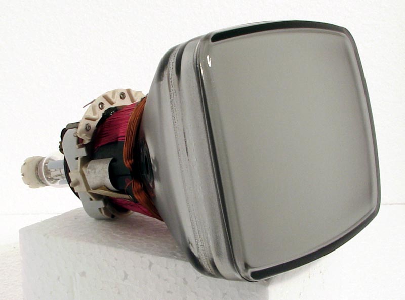
A small modern picture tube
The cathode ray tube is the only display device for high definition television reception which has reached the stage of mass-production. From the early work by J J Thomson and by F Braun in 1897, the development of the cathode ray tube has followed many diverging paths to produce widely differing tubes for many specialised purposes, but it is the purpose of this booklet to explain those aspects of cathode ray tube development and operation which apply to tubes intended for television picture reproduction, rather than for radar or oscilloscope displays.
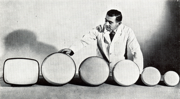
A group of early MAZDA television cathode-ray tubes with screen diameters of 7, 9, 12, 14 and 15 inches and a rectangular type with a screen diagonal of 17 inches
The study of the motion of electrons in vacuum (cathode rays) was first carried out in high voltage discharge tubes with cold cathodes. Electron emission in these tubes was induced entirely by high field strength at the cathode and consequently extremely high voltages were required. The early Thomson tubes were used to study the deflection of electron streams by electrostatic and magnetic fields and resulted in a determination of the ratio of mass to charge of the electron. It was soon realised that the deflection of a beam of electrons offered a method of measuring the strength of an electrostatic field and the Braun tube was the first attempt to produce a tube to act as a measuring instrument. These early tubes were restricted in their usefulness by the very high voltages needed for operation and by the extremely low beam currents available.
The introduction of the heated cathode to produce a supply of electrons by thermionic emission enabled tubes to be produced for operation at much lower accelerating voltages since the final anode served merely to accelerate the beam and no longer had to provide a high field strength at the cathode to induce emission.
Later developments have been directed towards providing a more copious supply of electrons from the cathode and towards providing a well focused beam at a high current.
In the early 1930s the cathode ray tube began to emerge from its role as an interesting laboratory novelty and began to be manufactured commercially. The Mazda (Ediswan) laboratories and factory at Ponders End, near London, where Professor Fleming's original diode valve was constructed, played an important part in developing the cathode ray tube for commercial manufacture. It was in this factory that the first commercial magnetically focused television cathode ray tube was produced in 1936.
Basic Form of the Cathode-ray Tube
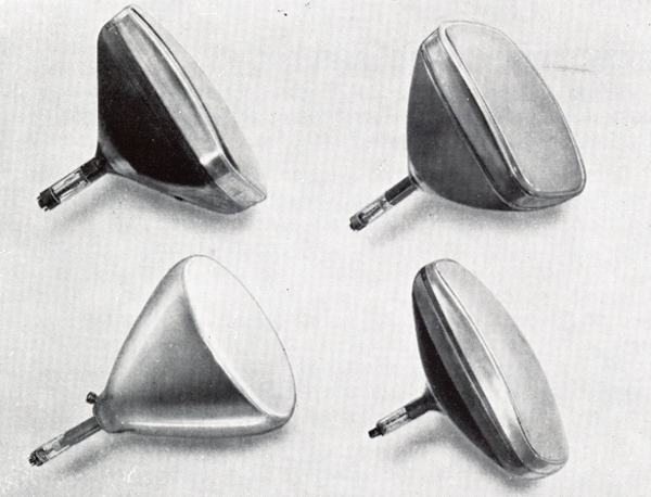
A selection of television cathode-ray tubes with screen sizes of 15 and 17 inches. The difference in periods of development accounts for the variety of cone shapes.
Any cathode ray tube may be considered in four sections:
- A system of electrodes to produce a beam of high velocity electrons including some means of controlling the intensity of the beam.
- A means of concentrating the beam to form a sharply focused point on the screen.
- A deflecting system to deflect the focused beam to anypart of the screen.
- A screen coated with fluorescent material which emits visible light when bombarded by high velocity electrons.
The whole arrangement is enclosed in an evacuated enclosure, usually of glass which may take a variety of shapes according to the purpose for which the tube is intended. The system of electrodes to produce the beam is often referred to as the electron gun. In tubes in which the focusing is carried out electrostatically the electrodes which carry out the focusing are usually built as part of this structure and the whole structure is then referred to as the gun, so combining (i) and (ii) above.
Motion of Electrons
Electrostatic Fields
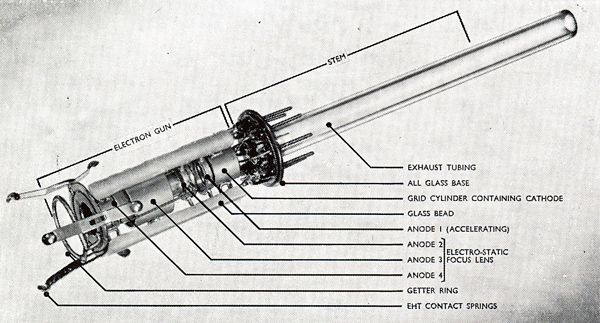
A CRT gun with electrostatic focus electrodes. When inserted into the bulb the three springs make contact with the internal conductive coating on the glass cone, which in turn connects to the EHT side contact. The glass exhaust tubing, shown on the right, is sealed and cut off on completion of pumping.
Before dealing with the CRT gun it is necessary to consider some fundamental points concerning motion of electrons under the influence of electrostatic fields.
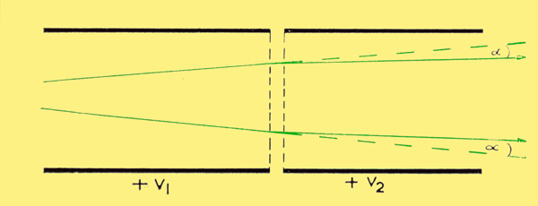
Bending of electron paths by an electrostatic field (V2 gt V1).
Consider the motion of an electron within a long metal cylinder which is terminated at one end by a fine wire mesh (see above). The cylinder is connected to a certain source of potential +V1. Just beyond the mesh is a similar mesh connected to a second cylinder at potential V2, +V2 is a higher positive potential than +V1. Inside the cylinder there will be no field (ie no variation of potential) so the electron path will be a straight line. Assume that this path is not parallel to the axis of the cylinder. On reaching the mesh it will have a component of velocity parallel to the axis of the cylinder (i.e. perpendicular to the mesh) and a component perpendicular to the axis (parallel to the plane of the mesh).
On moving through the meshes into the second cylinder it will be accelerated by an accelerating field perpendicular to the meshes. This field will act only on the component of velocity perpendicular to the mesh and not on the component parallel to the mesh. Thus the electron will enter the second cylinder with a greater component of velocity parallel to the axis of the cylinder and the original unchanged component of velocity perpendicular to the axis. Thus its path will make a smaller angle with the axis, the direction of motion having been turned through an angle depending on the ratio of the two potentials.
This behaviour is similar to the bending of a ray of light passing from one medium to a more dense medium. For two electrons whose paths are diverging in the first cylinder their paths in the second cylinder will be less divergent and the bending of the paths of the electrons is rather like the bending of rays of light when passing into a denser medium.
Equipotential Surfaces
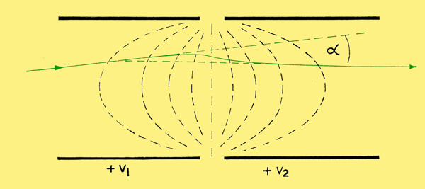
Motion of electrons between two open-ended cylinders (V2 gt V1).
Equipotentials are at interval (V2 - V1) / 10
If the meshes are omitted the bending is not abrupt but gradual (as above). In this case the potential for some distance inside the cylinders is far from uniform and it is possible to plot surfaces joining points of equal potential at various potentials between V1 and V2. Such surfaces are known as Equipotential Surfaces.
The image above shows a plane section through two cylinders including the axis of the system. The intersections of the equipotential surfaces with this plane are shown dotted in black. When an electron moves in a region of changing potential the force acting on it at any point in its path is perpendicular to the equipotential surfaces at that point. This is because the rate of change of potential (or electric field strength) is greater in this direction. In other words the electron experiences a pull trying to move it perpendicular to the equipotential surfaces in the direction of increasing positive potential.
Although the electron is extremely small it has a finite, measurable mass and hence, when in motion, momentum. Thus an electron in motion will attempt to continue in the same direction except in so far as the force perpendicular to the equipotential surfaces attempts to deflect it from its original path. At any point in the electrode system the speed of an electron depends uniquely upon the potential in the space at that point. Slow moving electrons in the low potential parts of the gun are more easily deflected from their paths than fast moving electrons in the high potential parts.
Shown in the above image, in the first part of the field there is a bending towards the axis and then a bending away from the axis but the overall effect is still one of convergence. The beam is turned through an angle alpha as compared with an electron travelling along the axis which would be merely accelerated without deviation.
This arrangement of two co-axial cylinders at different potentials constitutes an Electron Lens. Its behaviour can be compared to that of a normal optical lens composed of layers of gradually changing refractive index. For this reason the study of the formation and focusing of electron beams is often referred to as Electron Optics.
In the television cathode ray tube the source of electrons is a heated cathode comprising a cylinder, usually of nickel, closed with a flat disc at one end and having inside it a heating element coated with insulating material to insulate it from the cathode cylinder. The flat end face is coated with a mixture of the oxides of various elements which serve to increase the emission of electrons from the heated surface. Typical of the oxides used are those of Barium, Strontium and Calcium.
The Grid and Anode
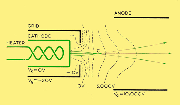
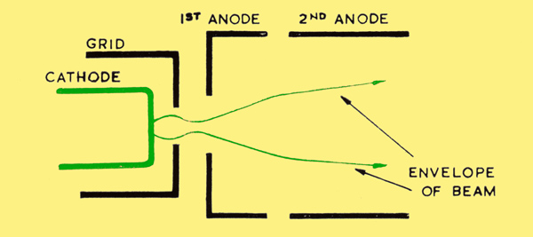
Triode gun with typical voltages and electron paths.
Associated with the cathode are a control electrode (often called the grid by analogy with radio valves) which is maintained at a potential slightly negative to that of the cathode and an anode which is at a positive potential with respect to the cathode. The grid or control electrode takes the form of a cylinder, co-axial with the cathode cylinder and closed at the forward end by a disc in the centre of which is a small hole of the order of half to three quarters of a millimetre diameter. The anode is also a co-axial cylinder and in some cases may have an apertured plate on the end.
Control of Beam Intensity
In the cathode ray tube all potentials are measured with respect to cathode potential which is taken as zero.
The form of the equipotential surfaces between grid potential -Vg and anode potential +Va is roughly shown dotted in the image above. The effect of this system is to cause the beam of electrons leaving the cathode surface to converge to a small cross section in the region C and then continue to diverge as the electrons accelerate into the anode region.
It should be noted that in all diagrams of electron guns the vertical dimensions of the electron beam are considerably exaggerated to emphasise the effects taking place.
Although emission of electrons is taking place over the whole of the area of the cathode face the useful beam current is drawn from only a small fraction of this area. If the grid is given a highly negative potential with respect to the cathode so that all beam current is cut off, the emitted electrons will be contained in a thin cloud covering the emitting surface, electrons leaving the cathode surface being balanced by electrons returning from the cloud to the cathode. If the grid potential is now gradually made less negative there will come a time when the zero voltage equipotential reaches practically to the cathode surface, a condition very much as illustrated above.
From the zero equipotential into the anode space the potential is increasingly positive so electrons entering this space will be drawn away as beam current. If the zero equipotential is made to approach close to the cathode, electrons will have sufficient energy to overcome the slight negative potential region in the immediate vicinity of the cathode, reach the zero equipotential and escape as beam current into the rest of the gun structure. A grid potential slightly negative of this critical value results in no beam current; grid potentials more positive result in a progressive increase in beam current. The critical value is referred to as Beam Cut-Off potential and is an important characteristic of any design.
As grid potential is made to approach zero, the zero equipotential approaches the cathode surface over a larger area and as beam current is increased the current is drawn from a larger area of cathode. When grid potential is made equal to cathode potential, current is drawn from a cathode area almost exactly corresponding to the area of the hole in the grid electrode. It is worth noting that although beam currents of television cathode ray tubes are small, usually much less than one milliampere, the current is drawn from a very small area of cathode so that the current per unit area loading is greater than that of many high power valves. This represents a very severe design condition and considerable attention has to be given to cathode processing.
Crossover Point
For any value of grid potential between cut-off and cathode potential the conditions as the illustration above apply. That is to say the electron stream first converges to a region of maximum density just beyond the hole in the control grid and then continues in a diverging beam into the anode space. In the various electron paths are shown crossing at a single point. In practice, due to variations in direction and velocity of emission from the cathode this is not true and the crossing points of the various paths lie within a small region of finite size. This region of maximum density, usually known as the Crossover is smaller than the area of cathode from which the electrons are initially drawn and can be regarded as a virtual source of electrons as far as the rest of the tube is concerned.
Triode Gun
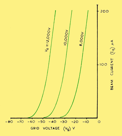
Characteristics of a typical triode gun.
So far, the production of a beam of electrons has been considered by means of a system comprising a cathode, a grid or control electrode and an anode. It has merely been stated that the anode is at a potential positive with respect to the cathode but it has not been considered whether the beam undergoes any subsequent acceleration by further electrodes.
In the early range of cathode-ray tubes the gun consisted merely of the electrodes so far described. The anode was connected to the final accelerating voltage of, say, 10,000 Volts and the electrode geometry was arranged so that under these conditions a negative voltage on the grid of about 50 Volts was sufficient to cut off the beam. This arrangement was known as a Triode Gun. However, there were some difficulties in the use of this scheme and further developments were introduced to overcome them. For example, if a tube was designed for use at say 10,000 Volts final anode voltage with a grid cut off voltage of -50 Volts its performance under these conditions would be very good. Suppose, however, that some user wished to produce a low price ''economy'' receiver working at say 8,000 Volts (see Fig. 7) or a better receiver at 12,000 Volts, then under these conditions the tube would have a cut off voltage different from that which was originally intended. The tube at 8,000 Volts would have a low cut off and less available maximum current at zero grid-to-cathode voltage whilst the tube at 12,000 Volts would have a high cut off voltage although certainly having more available maximum current (See the characteristic curves above).
Tetrode Gun
The tetrode gun
To overcome this variation of tube characteristic with final anode voltage, the arrangement illustrated in was adopted. This arrangement is often referred to as a Tetrode Gun structure. The first anode is maintained at a potential of 300 to 500 Volts with respect to cathode and, together with grid and cathode, constitutes a beam forming and control system similar to a triode gun. A crossover of high electron density is produced in the vicinity of the grid hole from which the electrons travel on in a diverging beam. Because of the small aperture in the first anode, the second anode, which is maintained at the final accelerating potential of several thousand Volts, cannot have much effect on the potential distribution in the grid-to-cathode region. This ensures that, provided the first anode potential is unchanged, the beam current-versus-grid voltage characteristic of the tube will be almost independent of final accelerating potential.
After leaving the first anode aperture, the electrons are accelerated to their final velocity by the final anode a2. The gap between the first and second anodes constitutes an electron lens such as was described earlier so that this acceleration is accompanied by a converging action which reduces the angle of divergence of the beam.
Focusing The Beam
It has been seen that the electron gun produces a diverging beam of electrons either by means of a triode system or tetrode system and the intensity of the beam can be controlled by the control grid-to-cathode potential. It has also been seen that the electrostatic field system between a pair of cylinders at different potentials produces a bending of electron paths much in the same way as a lens bends and concentrates a beam of light. It is convenient to consider the performance of the rest of the electron optical system in producing a focused spot on the screen as being analogous to the performance of an optical lens system. This would be an optical lens system projecting a focused image of a small intense source on to a screen. The small intense source is, in our case, the cross-over from which the electron beam appears to diverge.
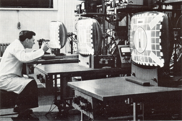
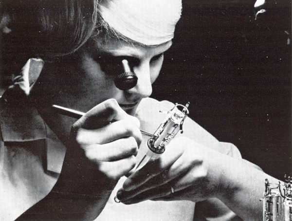
Laboratory examination of the focus performance of sample MAZDA tubes taken from the production line.
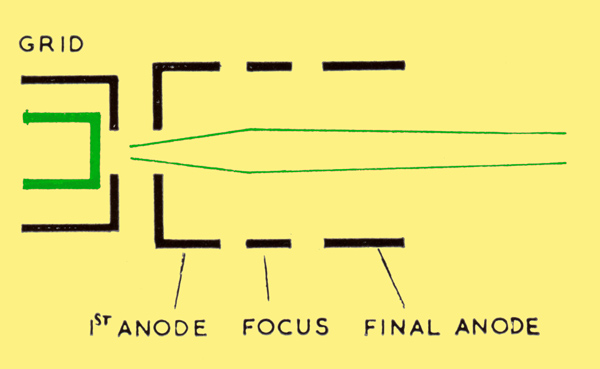
In the triode gun which was used in early television tubes such as CRM92, CRM121 and CRM151, the anode at a potential of several thousand Volts with respect to the cathode and the dimensions of the electrodes adjusted to give the required field configurations. After having penetrated some distance into the anode cylinder, the electrons have been accelerated to a high velocity and, having been formed into a divergent beam, then continue to travel each in its own straight path. At a suitable point a focusing lens is introduced and from this point onwards the beam converges to a final focus at the tube screen. The interior surfaces of the neck and bulb of the tube are coated with a conducting material connected to the final anode. This produces an enclosed region in which there is no variation of potential, so that after the focus lens the electrons travel in straight paths without change of velocity. This is illustrated below.
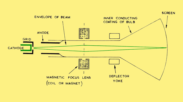
Diagram of a triode tube assembly
Magnetic Focus
In early television tubes and in some high quality tubes such as tubes for film scanning, the focus lens takes the form of an electro-magnet or permanent magnet producing, over a short region, a magnetic field parallel to the axis of the tube. This magnetic field acts to bend the electron paths towards the axis and by correctly adjusting the strength of the field, the point of focus may be made to occur at the fluorescent screen.
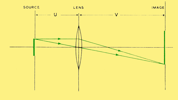
Equivalent optical system
Now, let us consider the optical analogy (shown above) in which a lens at a distance U from a small source of light forms an image of that source on a screen at distance V on the other side of the lens. The magnification, that is to say the ratio of the diameter of the image to the diameter of the source is given by the ratio V/U.
Thus a lens arranged to have a large image distance V and a small source distance U will give an image much larger than the source. The consideration of magnification applies to the electron-optical system of the cathode ray tube in exactly the same way as it applies to an optical lens system. In a cathode ray tube focus system the position of the focus lens must be arranged so that the magnification results in a spot size on the screen which is suitable for the use for which the tube is intended. For example, some tubes intended for very high definition radar use may demand a smaller spot size than a television cathode ray tube of similar screen size.
Electrostatic Focus
Early tubes for television reception used a magnetic lens for focus of the beam but it is equally possible to use an electrostatic lens. Indeed electrostatic lenses have been used almost exclusively in measurement tubes for oscilloscopes but it is only since about 1953 that they have been used in tubes for television reception. This change was introduced in the first place as an economic measure on account of high cost and scarcity of magnetic materials, but the simplification in receiver design brought about by the change has ensured the popularity of the electrostatic lens.
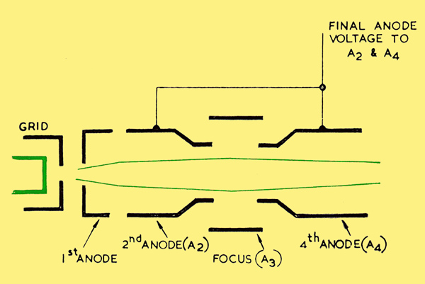
The Tripotential lens
There are several ways in which electrostatic focus can be carried out. It has already been noted that in a tetrode gun there is a converging lens formed by the gap between first anode and second anode and by strengthening of this lens it is possible to carry out all the focusing in this region. One method of doing this is to introduce a short cylinder between first anode and final anode so that by controlling its potential, the strength of the lens can be adjusted to the required value. This is illustrated and is often referred to as an acceleration or Tripotential Lens.
The Unipotential lens
An alternative scheme is illustrated above. Here the system of cathode, grid, first anode and second anode is adopted as before with some converging of the beam taking place in the region between the first anode at about 400 Volts and the second anode at several thousand. The second anode is extended to a greater length and at a suitable point it is split into two parts and the gap is surrounded by a larger diameter focus cylinder which is maintained at approximately cathode potential. It is usual to form the two ends of the final anode either side of this gap into nozzles facing one another. The beam leaves the first anode-second anode region diverging slightly as previously noted, having been accelerated to a velocity corresponding to the final anode potential. On entering the region of the gap in the final anode, the electrons see or come under the influence of the surrounding focus cylinder which is considerably negative with respect to the potential to which they have been accelerated. They are therefore repelled or squeezed towards the tube axis and this action achieves the final focusing. The potential of the focus electrode is varied to obtain accurate focusing. In this system electrons enter and leave the lens at the same potential and the system is known as a Uni-Potential Lens.
Just as in optical lens systems, electron lenses can suffer from aberrations such as spherical aberration, astigmatism, curvature of the field, etc., which deteriorate the sharpness of the focused spot and electrode systems must be designed to attempt to minimise these aberrations.
Beam Deflection
Magnetic Scanning
In order to display a television picture on the fluorescent screen the beam of electrons must be deflected rapidly in a horizontal direction and more slowly in a vertical direction so that the focused spot traces the familiar pattern of lines or Raster of which the television picture is composed. These deflections are carried out by two magnetic fields. A field in which the lines of force are vertical deflects the beam horizontally whilst a field in which the lines of force are horizontal deflects the beam in a vertical direction. The fields are produced by currents in two systems of coils placed around the tube neck at a point after the beam has left the focusing system and just before the neck merges with the cone of the tube.
The design of this system of coils or Deflector Yoke has a great influence on the quality of the picture for, not only can incorrect shaping of the magnetic fields cause geometric distortion, but the deflection process can also introduce defocusing of the spot. Unfortunately the requirements of good geometric shape are not the same as those of freedom from defocusing and the solution, as in so many engineering problems, is one of compromise.
Scanning Angles
In order to reduce the overall depth of television receivers, tube designers have progressively reduced the length of the tube by increasing the angle of deflection. The angle through which the beam must be deflected from one extreme of the picture diagonal to the other, has increased from about 500 in 1947 to 1100 in 1959. Intermediate values of deflection angle of 700 and 900 were used for short periods at various stages in the development. These changes were only made possible as circuit developments permitted the increased deflection currents to be generated economically. The historical development of tubes is summarised later.
Flatter Screens
These changes in deflection angle were accompanied by a gradual move towards flat tube faces which, on account of the pressure of the atmosphere on the evacuated bulb, made the design of the glass bulb very difficult. The more the shape of an evacuated bulb departs from a true sphere, the more difficult is it to make it withstand the pressure of the atmosphere. The magnitude of this problem can be appreciated when it is realised that the face of a 23 inch cathode ray tube such as the CME23031 AW59-91 is subjected by the atmosphere to a total weight of about one and three quarter tons.
The Fluorescent Screen
Phosphors
The inner surface of the tube face is coated with a material which emits visible light when bombarded by high velocity electrons, the colour of the emitted light depending upon the material used. Such materials are known as phosphors and usually consist of the silicates, sulphides, or oxides of zinc, cadmium or magnesium with small quantities of silver, copper or manganese as an impurity which behaves as an activator. The phosphors are in the form of imperfect crystals in which the activator ion has replaced one of the principal elements. Under bombardment electrons are energised to an excited state giving off light as they fall back, usually after a delay, to the original state.
Where The Beam Current Goes
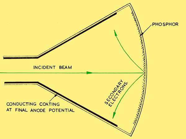
Internal bulb coatings in a non-aluminised tube
In the early television tubes the internal conductive coating of the inside of the bulb was only applied over the region from the gun to the edge of the screen to avoid contamination of the phosphor by the conductive material (colloidal graphite) then in use. As a result of this arrangement, negative charge deposited on the screen by the incident beam of electrons could only be removed by leakage through the glass to the conductive coating or by re-emission of secondary electrons from the phosphor which travelled through the vacuum to the conductive coating.
Failure of these processes to remove the negative charge resulted in the screen being at a potential well below that of the conductive coating with consequent loss of brightness. If these processes were less effective in one part of the screen than another potential would vary over the screen with consequent variation of brightness and geometric distortion of the picture.
Aluminising
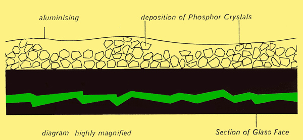
Section of tube face showing aluminising
These difficulties were overcome by coating the phosphor on the side facing the electron gun with a thin film of evaporated aluminium (above), this film being extended over the rest of the inside surface of the bulb to form the conductive coating. This resulted in a stabilisation of potential over the screen at a value equal to that of the final anode. This process is now used in all modern MAZDA Television cathode ray tubes. An additional advantage followed from this process. Light which was previously emitted backwards from the phosphor into the bulb is now reflected forwards from the mirror-like surface of the aluminium to increase brightness and contrast of the picture. It is true that some energy of the electrons is lost in penetrating the aluminium film but this is small and is more than offset by the gain in brightness under normal working conditions.
Overcoming Ion Burn
The bulb of the cathode ray tube is evacuated as thoroughly as is economically possible under mass-production conditions. Nevertheless, production variations in materials and evacuation sometimes result in the formation of heavy negative ions either by emission from the cathode or by collision of electrons with residual gas molecules. These ions are accelerated by the final anode and ultimately bombard the screen where, being in a chemically active condition, they combine with and poison the phosphor. This reduces the light output. The effect is aggravated by the fact that the heavy ions are hardly deflected by the magnetic deflection fields and so bombard only a localised region in the middle of the screen.
For a long period a system of combined electrostatic and magnetic fields was built into a suitable part of the neck to select only electrons for passage to the screen whilst harmlessly capturing ions in the neck. This was known as an Ion Trap. This system has now been largely abandoned and instead, the aluminium film over the phosphor has been thickened to a point where ions are effectively absorbed but electrons may penetrate with only a small loss of energy. This, combined with better evacuation has rendered the Ion Trap unnecessary.
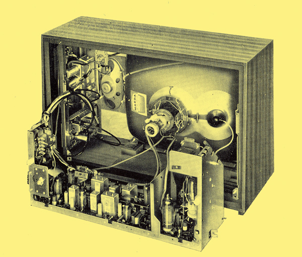
A MAZDA CME1903 19 inch picture tube fitted in a typical 1965 television receiver (HMV Model 2621). The scanning yoke is in place on the tube neck, but the printed circuit chassis is shown withdrawn.
Development
The features mentioned in this booklet may be illustrated by the development and growth of the MAZDA range of television cathode ray tubes as follows:-
Triode Guns with Magnetic Focus. Non Aluminised.
9MH 9 inch diameter screen. Deflection angle 45° 1936
12MH 12 inch diameter screen. Deflection angle 45° 1937
CRM121 12 inch diameter screen. Deflection angle 50° 1938
CRM92 9 inch diameter screen. Deflection angle 50° 1939
Triode Guns with Magnetic Focus. Aluminised.
CRM123 12 inch diameter screen. Deflection angle 50° 1950
CRM151 15 inch diameter screen. Deflection angle 50° 1950
CRM152 15 inch diameter screen. Deflection angle 70° 1952
Tetrode Guns with Magnetic Focus and Ion Trap. Aluminised.
CRM141 14 inch diameter screen. Deflection angle 70° 1953
CRM153 15 inch diameter screen. Deflection angle 70° 1953
CRM143 14 inch diagonal rectangular face. Deflection angle 70° 1955
CRM171 17 inch diagonal rectangular face. Deflection angle 70° 1953
CRM211 21 inch diagonal rectangular face. Deflection angle 70° 1955
CRM173 17 inch diagonal rectangular face. Deflection angle 90° 1958
CRM212 21 inch diagonal rectangular face. Deflection angle 90° 1956
Tetrode Guns with Electrostatic Focus and Ion Trap. Aluminised.
CME141 14 inch diagonal rectangular face. Deflection angle 70° 1957
CME1402 14 inch diagonal rectangular face. Deflection angle 90° 1958
Tripotential Guns. No Ion Trap. Aluminised.
CME1705 17 inch diagonal rectangular face. Deflection angle 110° 1959
CME2104 21 inch diagonal rectangular face. Deflection angle 110° 1960
Tetrode Guns with Electrostatic Focus. No Ion Trap. Aluminised.
CME1702 17 inch diagonal rectangular face. Deflection angle 90° 1958
CME1703 17 inch diagonal rectangular face. Deflection angle 110° 1959
CME2101 21 inch diagonal rectangular face. Deflection angle 110° 1959
CME1903 19 inch diagonal rectangular face. Deflection angle 110° 1962
CME2303 23 inch diagonal rectangular face. Deflection angle 110° 1962
These tubes do not comprise the entire range but have been chosen to illustrate the trend of development and changes in various principal parameters. Dates given are the years in which the tubes came into use by the public.
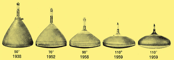
Progress towards shallower receivers
Return to Electrons Contents List
|