|
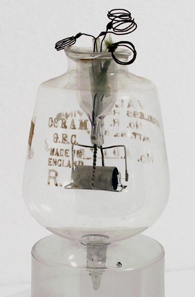
An example of the R2 without its candelabra cap
A simple heterodyne circuit satisfied most of the UK Naval receiver requirements during WW1. Basically, this was a one-valve self-oscillating mixer which provided an audible beat tone for the CW Morse transmissions. The R-Type was not suitable for this circuit because it was unable to oscillate over the full frequency range. At first, the Round Q valve was used, but this had the disadvantage of requiring a high voltage for the HT supply
By 1916, the BTH Company had made considerable progress in the development of the R-Type valve, based on the French TM design, and several trial batches were produced. By accident, one of these had a warped filament which brought the filament and grid closer together. This 'freak' valve was found to overcome the frequency limitations of the R-Type, but was not reproducible. After considerable work by Edmundson at BTH, a new valve the R4, was developed (naval version NR4). The R4 had a smaller grid diameter than the R-Type and its construction was similar to the R2A. Unlike the R2, it was pumped to a hard vacuum. The R4 met practically all the naval requirements for the heterodyne receiver during 1917.
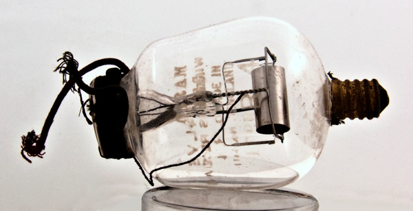
An example of the R.4
The R4 had a filament life of several thousand hours, some of them exceeding 8,000 hours. Unfortunately, the filament current of about one amp was quite high. This became more of a problem when two-valve receivers were introduced later in the War because of the added power drain on the low-tension batteries.
Filament research at the Naval Signal School in Portsmouth led to the R4A. This had a smaller diameter wire for the filament, which reduced the current to about 0.65 A. In order to provide the same emission, it was necessary to operate the filament at a higher temperature, which shortened its life to around 1,500 hours.
Because of its higher temperature filament, the R4A was quite noisy, thereby making it unsuitable for use in multi-stage amplifiers. The high noise was partly caused by the presence of thoria in the tungsten wire (added to make the tungsten less brittle). As a result, the R4B was developed which had a pure tungsten filament and this was less noisy. In 1919, the slightly improved R4C was introduced to replace all the previous types in the series.
Some physical details of the valves are given below.
Anode. Nickel sheet bent to form a complete cylinder of thickness 0.15 mm and diameter 9 mm. Length: R4 - 18 mm, R4A - 15.2 mm, and R4B - 15 mm.
Grid. Helix of 0.15 mm molybdenum wire, 3.5 internal diameter. Length: R4 - 20 mm, R4A - 19 mm, and R4B - 16.5 mm. Turns: R4 - 19, R4A - 16, and R4B - 19.
Filament. Straight tungsten wire, 1% thoriated for R4 and R4A, un-thoriated for R4B. Length: R4 - 26 mm, R4A - 22 mm, and R4B - 23.5 mm. Diameter: R4 - 0.088 mm, R4A - 0.061 mm, and R4B - 0.06 mm.
Base. Candelabra cap.
The principal manufacturer of the R4 series was GEC (Osram), later M-OV. Other manufacturers were BTH, Cossor and Edison Swan. The naval versions of the valves, with or without the prefix 'N', always carried the 'anchor' symbol on the glass bulb.
The general construction of the valves was very similar to the R2 series, with the candelabra cap for the filament wires and flying leads for the anode and grid wires. A sample found of the R4, manufactured by the MO Valve Company, was constructed in the more familiar bulbous glass with B4 base and an unused candelabra cap at the top, M-OV also produced the R4B with a B4 base.
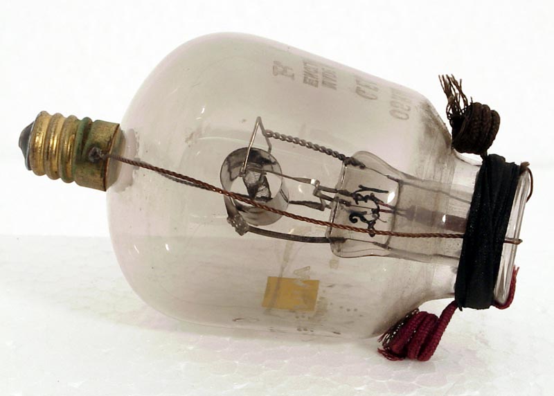
An example of the R5 with the candelabra cap
|