|
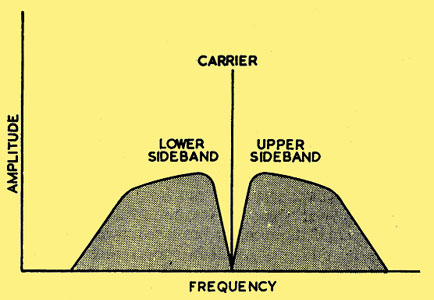
Frequency of an AM signal modulated with an audio signal
Normal Amplitude Modulated broadcast radio such as is to be found on Long and Medium Wave bands is easy to receive but not an efficient use of the transmitters power. Half of the radiated power is in the form of a fixed frequency carrier, and this carrier does not itself contribute to the program content.
Efficient use of transmitter power can be achieved by only transmitting one program sideband and suppressing both the carrier and the second sideband. This is known as Single Sideband or SSB for short. The downside is a more complicated transmitter and the need for a special demodulator in place of a simple diode detector that can be used for normal Amplitude Modulated signals.
A balanced modulator is a circuit that when balanced drives a transformer with equal and opposite voltages at radio frequencies. The effect of this application of equal and opposite sine wave voltages to the primary is that there is no output induced in the transformer secondary. Hence the term balanced. If an audio modulating signal is applied to one arm of the circuit its effect will be to add and subtract voltage from the radio frequency input to one side of the output transformer at an audio rate. This voltage upsets the balance of the circuit and the primary voltages will no longer cancel each other. The result is that the output circuit contains a radio frequency signal that has no central carrier at the RF frequency, but that will have RF output at plus and minus the audio modulating frequency. Such an output is known as double sideband suppressed carrier or DSB. Further narrow band filtering is employed to eliminate the second sideband.
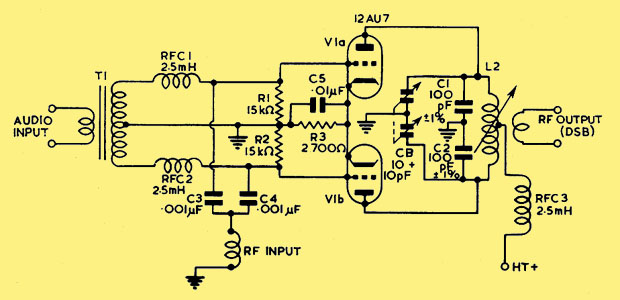
Circuit of a balanced modulator using a double triode
A pair of triodes can, and often were, used to make a balanced modulator. The circuit being essentially quite simple. The requirement was for very closely matched triodes and a balance control within the circuit. When correctly adjusted a suppression of 40 dB was easily possible. The problem with this arrangement is that even in a double triode valve, each half will age at a slightly different rate. The balance would decay over time due to this change in valve parameters. The costs of professional alignment of the transmitter at regular intervals reduced the attractiveness of the SSB equipment.
In America in the 1950s RCA set about a purpose designed balanced modulator valve. Consider the electrostatic deflection cathode ray tube. A single cathode assembly produces a pencil beam of electrons that are moved across the screen by voltages applied to the deflection plates. Each side of the screen will always receive a beam of the same strength as the beam is formed by a single electron gun. This general principle of a single beam of electrons would eliminate the differential ageing that altered the balance in a double triode balanced modulator. Low power types such as the 7360 and 6AR8 beam deflection valve were the outcome of the research.
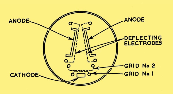
The RCA 7360 layout
The arrangement of electrodes in the 7360 is shown in above. A flat cathode, coated on one side, a control grid and a screen grid, form an electron gun which produces a ribbon-like beam. The screen grid and the two deflecting electrodes act as a converging electron lens to focus the beam. Varying the bias or signal applied to the control grid varies the anode current as in a conventional valve.
The total anode current, in the two anodes, at a given voltage is determined by the voltages applied to the control and screen grids (accelerator). The division of the total anode current between the two anodes is determined by the relative voltage difference of the two deflector electrodes.
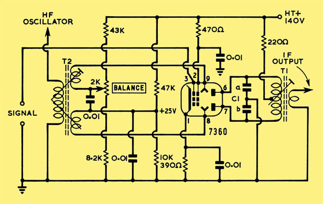
Use of the 7360 as a balanced modulator
The HF oscillator produces an AC signal that alternately gates the beam to the top and the bottom anode as shown in the circuit diagram. This has the effect of generating at the output a voltage at the HF frequency that cancels out at balance and generates DSB when the modulation is applied.
|