|
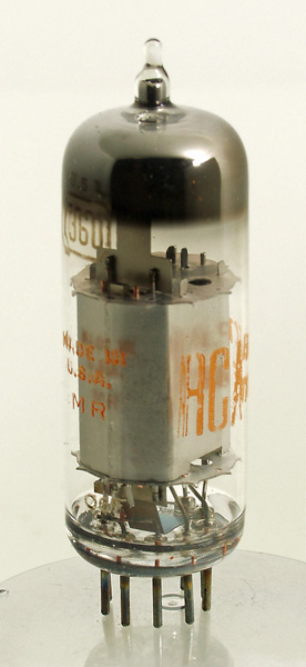
The RCA 7360 is a special beam deflection valve for the generation of SSB signals. A carrier suppression of up to 60 dB was possible, a very respectable figure.It is probable that this type of valve was developed from the UHF beam deflection mixer Type 1636 of 1944. The maximum ratings are not close to the typical operating conditions. Although the anodes can dissipate 1.5 Watts each, the operation is normally as a low power device. The anode voltage in balanced mixer operation would be typically 150 Volts and fed from a 250 Volt supply through 68k Ohm resistors. The screen grid would be operated at about 175 Volts. The deflecting electrodes operate at about 25 Volts each. The cathode resistor to generate the grid negative bias would be 1200 Ohms. The peak to peak deflecting AC voltage would be up to 8 Volts and the RF drive to the control grid tends to be 10 Volts. With these conditions the push-pull SSB output from the anode circuit would be in the order of 25 Volts peak to peak.A ribbon of electrons was produced by an electron gun and attracted to the two anodes, voltages on the deflection electrodes would alter the ratio of electrons reaching the separate anodes. Additionally stray magnetic fields would also deflect the beam in an unwanted way.In operation a carrier of up to 10 Volts peak to peak amplitude would be applied to the control grid g1 to modulate the numbers of electrons in the beam. An audio voltage of, say, 2.8 Volts pk-pk would be applied to one of the deflection electrodes. This would then sufficiently alter the ratio of electrons reaching the anodes to produce the wanted signal from the common anode transformer. The valve was used normally in the carrier frequency range of 0.5 MHz to 5 MHz.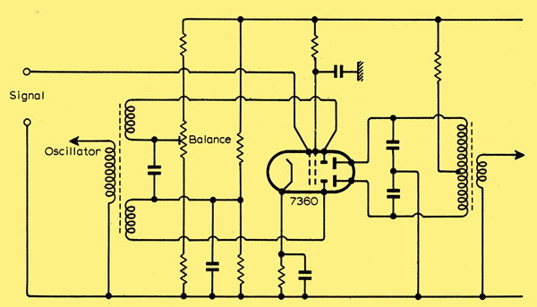
A balanced mixer of this form can provide low-noise and extremely wide dynamic range. The thin glass tube envelope is 20 mm in diameter and, excluding the B9A base pins, is 58 mm tall.Reference: Data-sheet & Wireless World June, 1970. Type 7360 was first introduced in 1961. See also 1961 adverts. |
Pin Connections
| 1 | 2 | 3 | 4 | 5 | 6 | 7 | 8 | 9 |  k,s | g2 | g1 | h | h | a2 | a1 | d2 | d1 |
|
|
Absolute Maximum Operating Conditions
| Vh | Ah | Va | Vs | 
| 6.3 | 0.35 | 300 | 250 |
|
Updated July 19, 2020.
|
|