|
Choosing the right components for the driver stage
In view of the remarkable performance of the new Class B battery valve, both as regards quality of reproduction and power output, it can safely be predicted that this type of output will be included in the majority of future battery sets. The choice of the correct driver valve and the calculation of the driver transformer ratio, among other points, are dealt with in detail in the accompanying article.
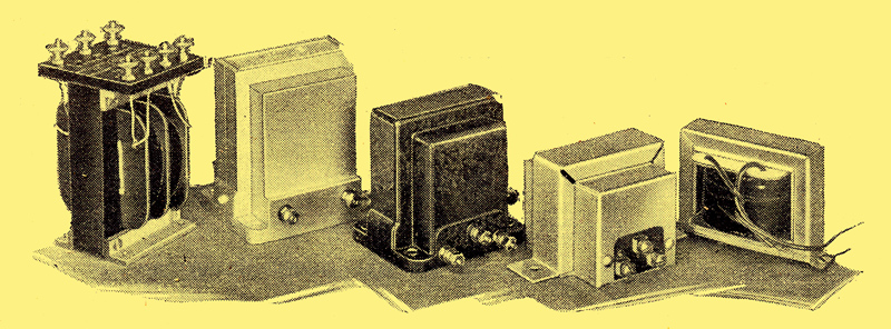
Five driver transformers with ratios from 2:1 up to 5:1 per half secondary. From left to right: RL, Lotus, Sound Sales, Benjamin & Trix
So many technical developments have occurred with the last few months that the most earnest student can be forgiven if he has difficulty in keeping abreast of each one. Take the case of Class B amplification, first described in The Wireless World but two weeks ago. Although the reader has been given a theoretical explanation of the new system, there are some practical aspects which need consideration. For instance, there are on the market numerous driver transformers necessary for feeding the Class B valve, some of which are shown in the illustration above. In a number of cases the overall ratio (total turns on primary to total turns on secondary) is 1 to 1, while in others the step-down ratio is 2 to 1, or even 3 to F, which is equivalent to 4 to 1 or 6 to 1 when we refer the primary to half the secondary, and the question arises as to which is the best type to choose for any given set of conditions.
Before a decision can be made it will be as well to remind ourselves of the somewhat strange conditions obtaining in an output stage where grid current is purposely made to flow. The two valves forming the dual Class B valve are each of the comparatively high-impedance detector type, and pass little anode current at zero bias, but, of course, run into grid current as soon as a signal is received. As each grid in turn becomes positive, electrons from the filament are collected by it, thus completing a current path across half the transformer secondary, making a partial short-current across it. Naturally, a complete short-circuit of the secondary would put the two ends at the same potential, destroying the signals entirely. A partial short circuit, on the other hand merely reduces the signal volts available.
Now to maintain full volts in face of the current drain through the valve, a source of power must be provided. This is effected, by a transformer deriving its power from a small output valve - the two together being known as the driver stage. From this it will be clear that output valve technique must be applied to the intermediate LF stage which precedes the output stag proper. How much power is required from the driver to make up for the losses incurred when grid current flows round the grid circuit of the Class B valve? It is not easy to work this out for ourselves, but the makers of Class B valves will always have to supply the figure, taking into account the DC resistance of the secondary of the driver transformer, the copper losses, etc. In a the case of the Cossor 240B valve, the driver must supply 70 milli Watts of undistorted energy if the full 2 Watts output is required from the loud speaker stage.
There are a large number of valves capable of delivering 70 milli Watts when working into the correct load which (where triodes are concerned) should be about twice the AC resistance of the valve. In the interests of anode current economy it has been found better to choose a valve rated for, say, 100 to 200 milli Watts and to bias it back until the reduced output is obtained. The type of small power valve with which this is possible nearly always has a gradual bend in the characteristic curve, and so the process of slight over-biasing does not introduce noticeable curvature distortion, especially when the input is small. Where rather more than the optimum bias is applied, the required anode load will, of course, be a little higher than the normal, because the valve's AC resistance will be increased.
This will explain why a suitable driver for the 240B is to be found in the Cossor 215P, which The Wireless World Valve Data Supplement tells us will deliver 150 milli Watts at 150 Volts HT, 7.5 Volts bias (10 mA anode current) when working into a load of 9,000 Ohms. At 120 Volts it will deliver 70 milli Watts when biased to 9 volts, and the anode current will be 2.5 mA, while the load will have to be a little more than 9,000 Ohms, say, 10,000 Ohms. The most sensitive valve for the driver stage would undoubtedly be one of the high-efficiency pentodes (220HPT, PT2, Pen220, or PM22A), but as the cost is just twice that of a small power valve, it is unlikely that it will find wide application.
The next problem is the choice of the correct ratio of driver transformer. Before we can tackle this we must know the minimum impedance of the grid-filament circuit of one of the members of the dual Class B valve. Obviously when grid current to the tune of many milliamperes is flowing the internal grid-filament path is highly conductive, and is equivalent to a resistance of quite a low value. Actually the figure for the 240B is 2,500 Ohms, and as only one half of the valve is in operation at any moment we are at liberty to ignore the other half. The secondary of the driver transformer being centre-tapped acts as a 2 to 1 auto-transformer, so the load across the whole winding is 22 x 2,500 = 10,000 Ohms. But this is the load we require for the anode of the 215P valve. We are thus left with the simple problem of transferring 10,000 Ohms from secondary to primary, necessitating, of course, a 1 to 1 ratio (or as some of the manufacturers put it 2 to 1 step-down ratio per half-secondary).
Had the driver valve required a load of 20,000 Ohms to give the necessary 70 milli Watts the driver transformer step-down ratio would have to be √2 = 1.4 (or 2.8 to 1 if referred to half the secondary). Again, a driver valve load of 40,000 would be given by an overall step-down ratio of √4 to 1 = 2 to 1 (or 4 to 1 per half-secondary), and so on. This explains why there are transformers on the market with overall ratios other than 1 to 1.
There are probably a number of readers who will find one Watt output sufficient for their needs, in which case the grid swing of the Class B valve can be restricted, and a loss of about 35 milli Watts only will have to be compensated. This can easily be handled by a detector-type driver valve consuming about 1.5 mA anode current, which, owing to its high impedance, will require a load of high value - an instance where a 4 to 1 or 6 to 1 step-down ratio (per half-secondary) will be required.
The transformer linking the 240B valve to the speaker must have a ratio such that the load across the primary is 8,000 Ohms (or rather more than this if a small driver restricting the output is used).
Take, for example, a speaker with a speech coil impedance of 2 Ohms; the output transformer ratio would have to be √8,000 / 2 = 63 to 1 step-down, and a speech coil impedance of 10 Ohms would require a ratio of 28 to 1. Fortunately, the majority of QPP output components already on the market are suitable.
It is interesting to note that because the grids of the Class B valve rob the anodes of current, the characteristic curves are similar in general shape to those of the screen-grid valve or pentode - this in spite of the fact that each half of the dual valve is a triode. The higher audio frequencies are, therefore inclined to be accentuated, and compensation is desirable. If, however, the usual filter is connected across the output transformer primary, anode current is consumed for the high notes which are shunted away. It is therefore better to control the tone before the driver valve, as this leads to an appreciable economy in anode current.
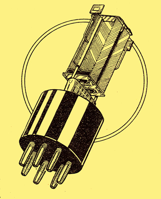
The Cossor 240B showing the two separate triode assemblies
As regards the sensitivity of the 240B output valve, a little more than 2 Watts can be obtained from a signal of 9 Volts peak applied to the driver valve - a highly satisfactory performance.
Class B amplification combines two virtues of great importance to the battery user: the first, an efficiency which is considerably greater than any other output stage, and the second, low cost, for the price of the dual valve is only 14/-.
|