|
Class B amplification while offering a marked saving in battery current is not without its special problems. In this article he effect of leakage inductance in the driver and output transformers is discussed and it is shown that by careful design reproduction of a very high quality is obtainable with this system.
The immediate effect of the introduction of Class B amplification into broadcast receivers has been the opening up of hitherto unrealised possibilities in the design and construction of economical battery sets. The term economical is used here to denote the type of set worked from the smaller types of dry batteries and consuming no more than 10 milliamps. Where cost of running is not an important consideration, good quality and volume can be obtained with Class A amplification by the provision of a large enough HT battery, but where this is not possible the need for limiting the average HT current consumption to about 10 milliamps rules out the possibility of obtaining sufficient output for any except the smallest rooms, as long as Class A amplification is retained for the output stage.
When the advantages of Class B amplification are available this drawback in economical battery operation largely disappears, for with the same average consumption of HT current the maximum power output is increased from about 0.2 Watt to 1 Watt. This is due, of course, to the fact that the Class B output valve consumes only enough current to reproduce the sound which is momentarily being amplified, while a Class A valve continuously absorbs enough current to handle the loudest undistorted output, even during quiet passages in the programme.
A few figures will serve to illustrate this point. In the case considered, where the peak output is about 1 Watt, A B21 valve working from a 120 Volt battery will take an average HT current of 6 or 7 milliamps, but a Class A triode working at the same anode voltage will require over 30 milliamps in order to be able to provide 1 Watt of AC power for the loud passages. The striking economy - 75% - resulting from the use of the B21 is responsible for the enthusiasm which designers of battery sets have felt towards this system of amplification.
Unfortunately, however, like most technical advances, Class B amplification is not without its difficulties, and the users of certain combinations of valves and transformers have in the past often been keenly disappointed in the tone-quality given by the new system. The harshness often noticeable in soft notes reproduced by this method was found to be all the more distressing by reason of the fact that the ear is accustomed to hearing such notes free from distortion ; this effect has been called 'Class B jangle', and by many experienced workers was believed to be inseparable from Class B amplification.
During the development of the B21 valve, investigation revealed the fact that the harshness already referred to was due to free electrical oscillations in the transformer windings and further that this tendency to oscillation could be reduced to an extent when it no longer spoilt the tone quality by careful attention to three points:
- The design of the output valve.
- The design of the transformers.
- The filter circuit.
The first point has already been cleared up in the design of the B21 valve, but in order to obtain really pleasing reproduction and the attendant economy in battery current with this valve, some little extra care and initial outlay in the matter of circuit components are needed.
With regard to the valve design, it was found that the high magnification factor of a zero-bias valve was particularly conducive to electrical oscillation. Accordingly, the magnification factor was reduced to a value such that, given reasonably good auxiliary components, the tendency to oscillate was sufficiently small. This accounts for the negative bias of 4½ Volts which the B21 requires. Incidentally there is another advantage in this, namely, that the valve can be biased to operate correctly over a much larger range of HT battery voltage than is possible with a zero-bias valve.
It is a familiar fact to radio amateurs that in a simple valve oscillator the tendency to oscillate is greater when the capacity is small, or the inductance large rather than vice versa. In many practical cases it has been found that the leakage inductance of the output transformer primary and its self-capacity constitute an oscillatory circuit. If the leakage inductance is kept as low as possible the tendency to oscillate will be much reduced. (It should be noted also that the same precaution ought to be observed in the design of the inter-valve transformer.) It might be supposed that the same result could be achieved by increasing the capacity in the oscillatory circuit by joining a capacitor across the transformer winding. It is true that some improvement can be secured in this way, but unfortunately it is found that by this means the frequency of the unwanted oscillation is reduced to a value at which the ear is very sensitive and in consequence the result is not so pleasing as one might suppose.
We shall now consider the design of the transformers in more detail. It is not intended that the following details should be regarded as hard-and-fast, but they can be relied on to give satisfactory results and enable the user to derive the full benefits of Class B amplification. Slight modifications of these designs have been used with success, although any attempt to secure extreme cheapness in construction is likely to lead to a reappearance of the harsh reproduction.

Fig. 1. - Dimensions of core stampings of Stalloy No. 4 and Laminic No. 70 from which the size of the bobbin for each style can be determined.
If a Stalloy core is used it should be of generous cross-section. The use of Sankeys'No. 4 Stalloy for both inter-valve and output transformers enables reproduction of the highest quality to be obtained. The core should be built up so that the centre member is of square cross-section. This will necessitate the building of a bobbin out of thin fibre or other insulating material like that shown in Fig. 1. The correct dimensions can be deduced from the diagram of the stampings in the same figure. In winding the inter-valve transformer, which has a centre-tapped secondary winding, the whole secondary is divided into four sections and the primary into two. The interleaving of these six coils confers freedom from flux-leakage and also electrical symmetry. The method of interleaving is shown in Fig. 2. This is brought about by first winding one section of the secondary (i.e., one-quarter of the total number of turns) on each side of the double bobbin shown in Fig. 1, following this by half the primary on each side. finishing up with the remaining half of the secondary divided between the two parts of the bobbin as before. All these coils should be wound in the same sense.
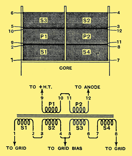
Fig 2. - A Theoretical arrangement of the winding on the driver transformer and the method of interleaving the sections on the bobbin.
It is assumed that the ends of the six sections have been brought through the bobbin cheeks. Reference to Fig. 2 will show the correct method of connecting these together.
The above description need not be repeated for the construction of the output transformer. It is only necessary to interchange the words primary and secondary.
If the Stalloy No. 4 stampings are found to be too bulky, equally good results may be obtained by the use of a smaller core of Laminic, a high-permeability alloy obtainable from Messrs. Magnetic and Electrical Alloys, Ltd., Lancelot Road, Wembley. A very satisfactory core can be built from No. 70 Laminic stampings (0.015 in. thickness, enamelled on one side preferably). The correct bobbin-size may be readily deduced from Fig. 1.
The correct wire sizes and number of turns are given in the table below. If the speaker impedance is different from 4 Ω, the transformer ratio is readily calculated from the approximate formula.
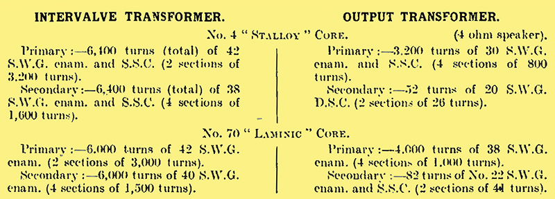
Total primary turns/Secondary turns = √ 12,000/Speaker Impedance.
In the above specifications, silk-covered wire can be used instead of enamelled, if a smaller wire-size is chosen, but, of course, a very slight drop in efficiency results.
Filter Circuit
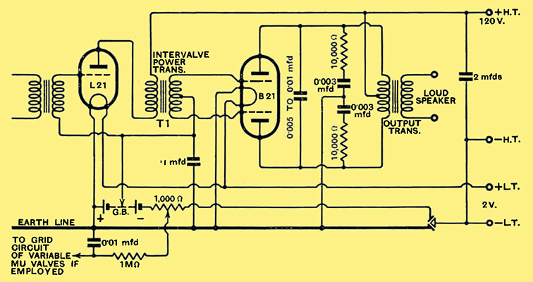
Fig. 3. The complete Class B stage, including all the refinements necessary for good quality reproduction.
This has an important bearing on the quality of reproduction, but Fig. 3, which includes the filter-circuit, is self-explanatory. The use of moving-coil speakers is strongly recommended for this type of output stage. The large reactance of the coils of moving-iron speakers is as much a disadvantage in this system as it is with QPP.
|