|
Parallel and Push-Pull Output Valves
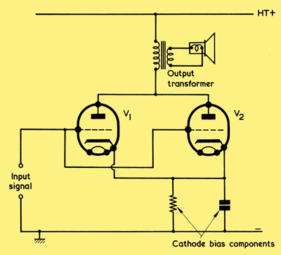
Two output valves may be connected in parallel to provide twice the output power that can be provided by a single valve. Triodes are shown for reasons of clarity, and the valves could alternately be beam tetrodes or pentodes.
In order to obtain a higher output than is offered by a single valve on its own it is possible to connect two output valves in parallel, as shown above. Both valves should, of course, be of the same type (e.g. two 6BW6s) and should be fairly well matched. Adequate matching would be given if, for example, two new valves by the same maker were used.
The two valves in parallel provide twice the output power that is offered by a single valve, and for the same grid input signal voltage. The impedance presented to the anodes by the output transformer should be half the optimum impedance for a single valve. The overall ra is half that of a single valve, and the total anode current will be twice that for a single valve.
It is assumed that cathode bias is employed, both cathodes sharing a single bias resistor and bypass capacitor. The bias resistor should have half the value that would be required for a single valve because twice the current is now flowing through it. This enables the bias voltage applied to both valves to be the same as for a single valve. Alternatively, the cathodes may have separate cathode bias resistors and bypass capacitors, each resistor having the same value as for a single valve.
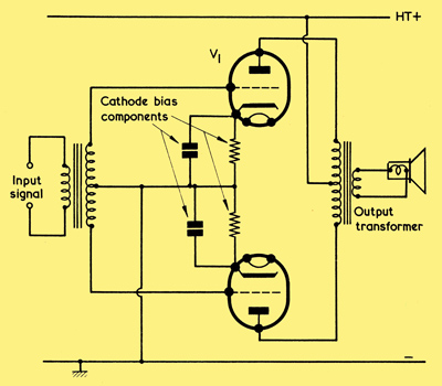
Two output valves may also be connected in push-pull as shown here.
Above we have two output valves in push-pull. The input signal to these two valves is provided by the centre-tapped secondary of a transformer, with the result that, when one grid goes positive, the other grid goes negative. Thus, the two signals at the grid are in anti-phase. The amplified signals at the anodes are similarly in anti-phase and are recombined in the centre-tapped primary of the output transformer, whose secondary couples to the loudspeaker in normal manner.
For normal Class A1 operation, each valve of of the push-pull pair may have the same bias voltage and anode load impedance (presented by the half of the output transformer primary between the centre-tap and the anode) as for a single valve, whereupon the output power is twice that for a single valve. The grid-to-grid input signal voltage (i.e. the signal voltage across the entire secondary of the input transformer) is twice that which would be required by a single valve. As the anode current of one valve increases during the input signal cycle the anode current of the other valve decreases, and it is from this method of operation that the term push-pull derives.
The push-pull output circuit has a number of important advantages. When an output valve is employed on its own it can provide an output which is a distorted version of the input signal applied to its grid. If the input signal is a sine wave, the distorted output signal will consist of the original sine wave plus harmonics of the sine wave, the latter having been generated due to the distortion introduced by the valve.
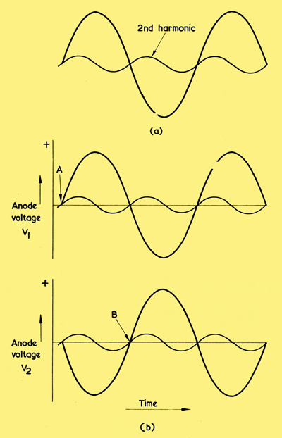
(a) A sine wave accompanied by a second harmonic.
(b) The two waveforms shown here could be present at the anodes of a push-pull pair. This diagram shows that, whilst the original sine waves are in ant-phase, the second harmonic signals are in phase.
To give an example, (a) shows a sine wave with a second harmonic, and it will be readily observed that this second harmonic has twice the frequency of the original sine wave. In (b) we see two sine waves which are in anti-phase, both having the same second harmonic. Such signals could be present at the anodes of the push-pull amplifier. It should be noted that the second harmonic has the same phase relationship to the original sine wave in both instances. At point A in the upper waveform the second harmonic starts to go positive at the same instant as does the sine wave, and the same occurs at point B in the lower waveform.
As was just mentioned, the waveforms of (b) could appear at the anodes of the push-pull amplifier. The two sine waves are in anti-phase (one goes positive when the other goes negative) which is the (desired condition for feeding to the ends of the centre-tapped output transformer primary. At the same time the two second harmonic signals are in phase (one goes positive when the other goes positive). Thus, on application to the ends of the centre-tapped output transformer primary they cancel each other out, and no second harmonic signal appears in the output transformer secondary.
The push-pull output circuit has the advantage, therefore, that any second harmonics introduced by distortion in the output valves are cancelled out in the output transformer. By following a similar procedure to that illustrated in (b), it can be shown that any further even harmonics (4th, 6th, etc.) which may be introduced by the output valves are also cancelled out in the output transformer. Unfortunately, the phase relationship given with even harmonics does not apply to the odd harmonics (3rd, 5th, etc.), These are not cancelled out and they appear in the output transformer secondary.
It should be added that, for good cancellation of even harmonics, both output valves should be nearly identical in characteristics and there should be a tight inductive coupling between the two halves of the primary.
Another advantage resulting from push-pull operation is due to the fact that the DC component of the anode currents of the two valves flows in opposing directions through the two halves of the output transformer primary. In consequence, the magnetic fields set up by the two halves of the primary due to this DC component are equal and opposite, and they cancel out. The DC component of the anode currents exerts, therefore, no magnetising force on the iron core of the output transformer. This is quite a different state of affairs to that given when a single output valve (or two output valves in parallel) is coupled to an output transformer. With the single valve there is always a DC component flowing in one direction through the primary of the output transformer, and a significant magnetising force is exerted on the transformer core in consequence.
Output transformers intended for operation from a single output valve usually have the laminations which form the core butt-jointed, with a gap to break the magnetic circuit.
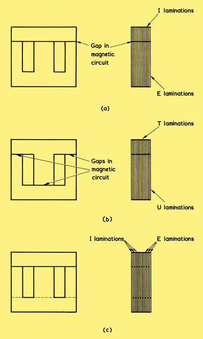
(a) Output transformer laminations in a butt-joint assembly
(b) A butt-jointed assembly with U and T laminations
(c) E and I laminations in an interleaved assembly.
A typical example is given in (a) in which E and I laminations are shown. All the E laminations are on one side of the assembly, and all the I laminations are on the other side, a piece of thin card or similar non-magnetic material being inserted between the sets of laminations to prevent a complete magnetic, circuit being set up.
In some butt-jointed transformers, no card or similar material may be inserted between the sets of laminations, an effective gap resulting from the relatively rough lamination edge surfaces which butt together. Also, the two end laminations may be fitted the other way round to ease assembly problems.
The gap in the magnetic circuit keeps at a relatively low level the flux density in the core which results from the DC component of the anode current, and it thereby prevents the core approaching saturation during the output half-cycles when the AC component of the anode current adds to the DC component. The butt-jointed type of assembly may also be used with U and T laminations, as illustrated in (b). Here, all the U laminations are on one side and all the T laminations are on the other side, with thin card or similar material interposed as shown in the diagram.
With a Class A1 or A2 push-pull output stage, there is no magnetising force due to the DC component of the anode current, and it is not necessary for the laminations in a push-pull output transformer to be butt-jointed. They can, instead, be interleaved, as shown in (c). Here there are alternate E and I laminations (or U and T laminations) on either side of the assembly with no gap in the magnetic circuit.
Since the laminations in a push-pull output transformer are interleaved, they offer a higher permeability than does a butt-jointed assembly of similar dimensions. Because of this, the push-pull output transformer can have a greater efficiency than a single valve output transformer of the same size. In practice, this would result in the push-pull output transformer introducing less distortion than the single valve output transformer.
Yet another advantage conferred by the use of a push-pull output stage is that, if both halves of the circuit are identical and the valves work in Class A1 or A2, a constant current is drawn from the HT positive supply rail. As the current drawn by one valve increases during the input signal cycle, the current from the other valve decreases by a similar amount. Since no currents at signal frequency flow in the HT supply applied to the output circuit, HT bypass and decoupling requirements become eased.
Summing up, it may be seen that we can use two valves to obtain twice the output power that would be given by one by either connecting them in parallel or in Class A1 or A2 push-pull. Connecting the valves in push-pull has the advantages that even harmonics are cancelled out (thereby reducing distortion), that a more efficient output transformer may be employed (again reducing distortion) and that HT bypass and decoupling requirements are less stringent. The advantages conferred by push-pull operation makes this the preferred choice when two output valves are to be used.
In push-pull circuit diagram the two grids of the push-pull output stage are supplied with anti-phase signals by way of a transformer having a centre-tapped secondary. In most cases, it is preferable to employ a valve rather than a transformer to provide the anti-phase grid signals, and we shall be discussing the circuits generally employed in a later.
|