|
Class A Output Stage
An output valve is, in general, the valve in an electronic circuit whose function is to couple the signal generated by that circuit to an external transducer, the latter being any device which converts electrical signal energy into some other form of energy. A loudspeaker is a transducer because it converts electrical signal energy into mechanical energy, the latter producing compressions and rarefactions in the air, which we hear as sound. It was, of course, to a loudspeaker that the output valve is coupled.
The output valve is required to provide an adequate level of power in order that the sound from the loudspeaker will be sufficiently loud. This is quite a different function to that of an AF voltage amplifier, which amplifies signal voltages at low current levels, and with which very little power is involved. In addition to feeding an AF signal at adequate power to the loudspeaker, the output valve also provides amplification as well.
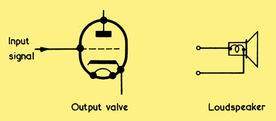
An output valve (assumed to be a triode) and a loudspeaker.
Above we see a valve which we intend to use as an output valve in a sound radio receiver. An AF signal is applied to its grid and we wish to couple its anode to the loudspeaker, which is also shown in the diagram. We may look upon the valve as an AC generator and the loudspeaker as a load whereupon, to a first approximation, we could have the circuit configuration shown below.

Replacing the valve with an AC generator, and the loudspeaker by a resistive load.
In the diagram the generator connects directly to the load. Note that the generator has an internal resistance, this being shown as a physical resistor connected in series with it. Since the generator is actually the valve, this internal resistance will be equal to the anode ac resistance, or ra of that valve. Previously we examined the question of matching an AC generator to a load, and we found that maximum transfer of power to the load occurred when the load resistance was equal to the internal resistance of the generator. In our diagram, maximum transfer of power would take place, therefore, if the two resistances happened to be equal in value. If the two resistances are different, maximum transfer of power can still be achieved by interposing a matching transformer, the square root of the transformer turns ratio being equal to the ratio between the two resistances. In the present case it will definitely be necessary to provide a transformer because the generator internal resistance will be of the order of tens of kilohms (which is the sort of ra figure to be expected from a valve suitable for output purposes) whilst the load would need to be represented as a resistor having a value, for typical moving-coil loudspeakers, of 3Ω or 15Ω.

How a matching transformer may be interposed between the generator and the load.
The transformer is introduced in the diagram above. In it the transformer would have a step-down ratio equal to the square root of the ratio between the ra and 3Ω or 15Ω, as the case may be, whereupon the circuit will provide maximum transfer of power to the load. Another way of looking at the operation of the circuit is to say that the primary of the transformer above presents an effective load to the generator (at points X and Y) which is equal to the generators internal resistance.

Reintroducing the valve and loudspeaker. The matching transformer ratio which provides maximum transfer of power does not correspond to that which gives maximum transference of power at an acceptable distortion level.
Now we reintroduce the original valve and loudspeaker. Keeping the same transformer turns ratio that we had before, we then have the situation where the primary of the transformer presents an effective resistance to the valve anode which is equal to the ra of the valve. Maximum transfer of AF power should, in consequence, take place.
Acceptable Distortion
There are, however, complications which upset this simple state of affairs. Firstly, whilst there may well be maximum transfer of AF power to the loudspeaker with the transformer ratio we have chosen, this does not necessarily mean that there will be maximum transfer of power at an acceptable level of distortion. With practical output valves it is found that, for a given level of maximum permissible distortion, say 10%, maximum transfer of power occurs when the load presented to the anode by the transformer primary is quite some way removed from the ra of the valve. Secondly, the loudspeaker cannot be looked upon as a simple resistive load, as was illustrated before. A moving-coil loudspeaker is quite a complex impedance, and it has different values at different frequencies. In point of fact, the nominal impedance quoted for a loudspeaker is, usually, the impedance it offers at 400 Hz.
Both of these factors, of which the first has greater weight, have to be taken into account when finding the optimum load which may be presented to the anode of an output valve for reproduction at an acceptable level of distortion. For simple general applications, fortunately, it is not necessary for the amplifier designer to find the optimum value for output anode load, because the valve manufacturers already specify this figure in their literature. The optimum anode load figure recommended by the valve manufacturers can then be used for calculating the ratio of the transformer needed to couple the anode to a moving-coil loudspeaker. With most output pentode and beam tetrode valves, the optimum anode load figure for acceptable distortion lies between one-seventh and one-tenth of the ra figure for the valve.
It will be helpful now to work out an actual example of finding the ratio required in a transformer used for coupling an output valve to a loudspeaker. A typical output valve is the EL84 pentode, for which its manufacturers specify an optimum anode load of 5,200Ω. We wish to couple this valve to a loudspeaker having a nominal impedance of 3Ω. Working from what we have just discussed the turns ratio required in the transformer will be the square root of 5,200/3 which (dividing the upper figure by the lower) is the same as the square root of 1,733. This square root works out at 41.6, which means that the transformer required should have a step-down ratio of 41.6:1. In practice, it would be satisfactory to use a transformer having a ratio of 40:1, this being sufficiently close to the calculated ratio.
Several further points need to be mentioned before closing on this particular subject. In valve manufacturers literature it is usual to find the optimum load resistance quoted under a heading such as Operating Characteristics or Operating Conditions. The optimum anode load figure may be referred to as Ra, the capital letter R being used because the quantity is outside the valve. Output transformers intended for home-constructor applications are often advertised in terms of primary and secondary impedances instead of in terms of ratio. Thus, a transformer advertised as having a primary impedance of 5,000Ω and a secondary impedance of 3Ω will be quite suitable for coupling an output valve for which the optimum load figure is 5,000Ω to a 3Ω moving-coil loudspeaker. In this case there is no necessity to work out the actual turns ratio. (The 5,000Ω to 3Ω transformer would, incidentally, be quite satisfactory for the EL84 we referred to just now). Other specifications for an output transformer include the maximum anode current its primary winding may safely carry, together with the maximum output power at which the transformer should be used. The anode current (in mA) and output power (in Watts) may be ascertained from checking the valve manufacturers literature for the particular output valve to be used.
We have already referred to the transformer coupling the output valve anode to the loudspeaker as an output transformer. It may also be described as a speaker transformer.
Class A Operation

Illustrating Class A1 operation, in which the grid is always negative of the cathode.
It is possible to operate an output valve under a number of different bias and input signal voltage conditions. Up to the present we have only dealt with voltage AF amplifiers, and these are biased in the manner illustrated above, in which diagram the input signal is applied, at the bottom and along the Vg axis, to the IaVg curve for the valve. The corresponding output signal is drawn at the right. The process used to construct the output signal in the diagram is graphical: lines are drawn vertically from the input waveform up to the IaVg curve, then continued horizontally to produce the corresponding output waveform. Note that the input signal is a voltage and the output signal is the corresponding anode current.
The input signal in the diagram above swings positive and negative of the bias voltage applied to the valve and is at all times applied to the linear (straight line) part of the curve. In consequence, the output waveform corresponds exactly to the input waveform. Also, the input waveform never causes the grid to go positive of its cathode (that is, to go positive of the zero grid voltage point on the Vg axis) with the result that there is no flow of positive grid current. Also, the input signal does not cause the grid to go beyond cut-off, or to approach the curved section, near cut-off of the characteristic.
An amplifier valve working under the conditions illustrated in is described as a Class A1 amplifier
In practice it is rare for an IaVg curve to have a section which is exactly linear, there being some slight curvature even on the straightest part of the curve. It is, however, readily possible to identify the most linear (straightest) part of an IaVg curve, and if the input signal is applied to this most linear part in the manner shown then the valve is described as a Class A1 amplifier.
All AF voltage amplifiers operate as Class A1 amplifiers. So do output valves for radio receivers, if they use the typical circuit values. Since no positive grid current flowed at any time during the input cycle, it was possible to obtain the input signal for our output valve from a preceding voltage amplifier. This is a normal practice for radio receivers using valves.
An IaVg curve continues to be linear after it has passed to the right of the zero grid voltage point, whereupon an alternative type of Class A operation becomes feasible. This is shown below wherein the more positive parts of the input cycle cause the grid to go positive of its cathode.

In Class A2 operation, positive grid current flows during part of the input positive half-cycle.
The input waveform is still applied to a linear (or very nearly linear) section of the IaVg curve, but it is obvious that, in this instance, positive grid current flows during the more positive parts of the input cycle. Because of this the preceding valve will have to be a power amplifier type in order that the correct input waveform shape can be maintained even when grid current flows. The preceding valve could not be a voltage amplifier because its output waveform, would become heavily distorted at the onset of grid current.
An output valve operated in the manner shown is described as a Class A 2 amplifier, the figure 2 indicating that grid current flows over part of the input cycle. This is as opposed to Class A1 operation, in which the figure 1 indicates that no grid current flows. Class A2 operation is only employed with valves which deliver power to a load, and never with voltage amplifiers.
Operation in Class A2 is not attractive for the output stages of radio receivers because of the necessity of preceding the output valve with a valve capable of developing sufficient power to drive the grid. It is a much simpler matter to use an output valve in Class A1 and precede it with a voltage amplifier.
Since Class A2 operation is used infrequently in radio receiver/domestic audio work some texts do not mention this method of working at all, referring only to Class A amplification without any subscript figure. Unless otherwise stated, a reference to Class A amplification can normally be assumed to apply to Class A1 working.
|