|
Basic Valve Circuits
We shall now consider some of the basic circuits in which a triode may be employed.
Driving a Loudspeaker
The alternating voltage amplified by a triode valve is frequently an audio frequency voltage. We saw a typical instance of this application in the last article which showed a carbon microphone coupled to the grid of a triode. When an audio frequency voltage is applied to a triode, or to several triodes in cascade, we will, for normal applications, require that the amplified signal be reproduced in a form which can be perceived by the ear. An obvious device for this purpose is the loudspeaker.
It is quite possible for a triode valve to drive a loudspeaker but it is necessary to ensure that the impedance presented to the triode anode is such that a satisfactory amount of power is fed to the loudspeaker. This is rather a different concept from the voltage amplifier we considered last month, because the latter was only required to provide an alternating voltage across a resistor. In the present instance we require that a significant amount of power be applied to the loudspeaker, and we refer to the amplifying valve as a power amplifying valve in consequence.
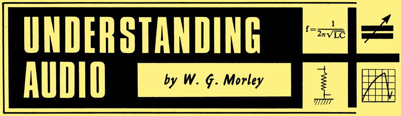
For reasons which we shall examine in a later article, a power amplifier valve offers best performance in terms of efficiency and low distortion when a particular load impedance appears in its anode circuit, the value of this load impedance. depending upon the valve type employed. The optimum load impedance is listed in the manufacturers technical information on the valve, in which the term 'load impedance' may be abbreviated to Ra (it being assumed that the impedance is resistive). Let us assume that, in the present example, we shall employ a triode which requires an anode load impedance of 5kΩ. At the same time, the loudspeaker we shall use with the triode is a moving-coil type having an impedance of 3Ω. No great problem is involved in coupling the loudspeaker to the valve, and all we need is a step-down transformer whose ratio is such that the impedance presented by the primary is the 5kΩ required by the valve. The transformer is connected as shown below.
Coupling a triode power amplifying valve to a loudspeaker by way of a speaker transformer. A grid bias battery is shown, but cathode bias could be employed just as readily.
The impedance presented by the primary of the transformer in will be equal to the secondary load impedance (the 3Ω of the loudspeaker) multiplied by the square of the primary-to-secondary turns ratio. If we call this ratio N, then:-
Zp = N2Zs
Rearranging the equation to bring N over to the left hand side, we get:-
N2 = Zp/Zs
∴ n = √(Zp/Zs)
Whereupon, we may see that the ratio is the square root of the required primary impedance divided by the secondary impedance. In our present example the required primary impedance is 5kΩ, or 5,000Ω and the secondary impedance is 3Ω so:-
N = √(5,000/3) = √(1,667) = 41
The transformer should, therefore, have a primary- to-secondary turns ratio of 41:1. In practice, ready-wound transformers generally available for loudspeaker use have round-number ratios of 40:1, 50:1, 60:1 and so on, and it would be quite in order to employ a 40:1 component for the simple application just described. (This last point applies, mainly, to home-experimenter and small-scale production applications. A large-scale manufacturer of sound reproducing equipment - including radio and television sets - would have transformers wound to suit his designs, and these could well be given turns ratio figures which do not fall into the 'round-number' category.)
The transformer is usually described as a speaker transformer, and it is a component specifically manufactured for the application. The anode current of the triode flows through the primary, varying in amplitude according to the alternating voltage applied to the triode grid. The current flowing in the primary can, in consequence, we described as a direct current on which is super-imposed an alternating current. Only the alternating current appears in the secondary, for application to the loudspeaker. An important point is that the transformer primary has to be wound with wire which is sufficiently thick to pass the anode current without overheating or burning out, and a necessary specification for a speaker transformer is the maximum direct current which may flow in its primary. Because of the direct current in the primary, speaker transformers intended for operation in the circuit above have their laminations butt-jointed rather than interleaved. Butt-jointed construction (which would, for instance, be given by having all E laminations on one side and all I laminations on the other side) prevents the core from approaching saturation as closely as would occur with interleaved laminations (alternate E and I laminations on each side).
It should be mentioned that, in the earlier days of radio, it was a very common practice to employ triodes as power amplifier valves driving loud-speakers, these valves being designed to pass higher anode currents than triodes intended for operation as voltage amplifiers. Nowadays, however, it is the custom to use more complex valves for power amplifier applications, as these enable higher efficiencies to be achieved. A speaker transformer is still employed to couple the valve to the loud-speaker, and the procedure for finding the ratio it should have remains. unaltered.
A final point is that a valve driving a loudspeaker in a circuit such as that above may also be described as the output valve (of the sound reproducing equipment in which it is fitted). The speaker transformer may, similarly, be called the output transformer.
Inter-valve Coupling
Since it is possible to employ a transformer to couple a power amplifier valve to a loudspeaker it would appear that such a component could, with advantage, be used between two valves in an audio frequency amplifier. The obvious advantage given by the transformer is that it could be a step-up type, and could therefore increase the overall amplification provided by the two valves.
Transformers were frequently used for inter-valve coupling in sound reproducing equipment before the war and, since the principles involved are still applicable, we will now briefly review the circuits employed and their advantages and disadvantages.
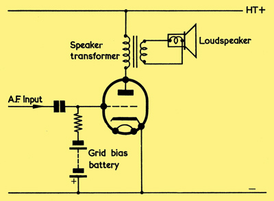
(a) Coupling one audio amplifier valve to the next by way of an inter-valve transformer. The grid and cathode circuits of the first triode and the anode circuit of the second triode are not shown, and may take up any of the forms already described
(b) The triode following the inter-valve transformer may have cathode bias, as illustrated here. The cathode bias capacitor is shown as an electrolytic component, as is normal for audio amplifier applications.
(a) shows a transformer coupling one audio amplifying valve to the next. The transformer could, in a practical circuit, have a ratio of the order of 1:6, whereupon the output from the amplifier will become six times greater than would have been given had resistance-capacitance coupling (which, of course, offers no increase in signal amplitude) been used instead. It will be noticed that grid bias is applied by way of the secondary of the transformer. As with the speaker transformer in the previous circuit, there is no flow of direct current in the secondary winding, and it may therefore be considered as a generator providing a stepped-up version of the alternating voltage at the anode of the first valve. An alternative, and equally suitable, method of biasing would be given by the cathode bias circuit of (b).
The main advantage of the coupling transformer, as already stated, is that it provides an increase in the overall amplification offered by the amplifier. A second advantage is that the primary of the transformer has a low resistance, with the result that the anode of the first valve has a higher high tension voltage than would be given with resistance-capacitance coupling. This advantage can be useful if the available high tension supply voltage is low compared with the requirements of the first valve. On the debit side is the fact that the transformer has to deal with alternating voltages ranging over the whole audio band of frequencies, which means that it requires a high permeability in its core to prevent attenuation (ie diminution) of the lower audio frequencies, and low self-capacitances in its windings to prevent attenuation of the higher audio frequencies. (Too low a permeability in the core could result in too low an inductive reactance in the transformer primary at the lower audio frequencies. In the high frequency case, the reactances offered by the self-capacitances could become sufficiently low at the higher audio frequencies to be comparable with the inductive reactances of the transformer.) There are other, more complicated, factors which can also cause a degradation in the audio frequency signal applied to the transformer primary, and these all add to the fact that, if the audio frequency signal is not to be seriously distorted from its original form, the transformer has to be a carefully designed and relatively expensive component. It follows that, if a cheap component is used then quite significant distortion may result.
A further disadvantage of the transformer when used for inter-valve coupling in an audio amplifier is that, unless it is efficiently shielded, a magnetic field appears about it, and this may interact with other inductive components. Or, again, currents may be induced in the transformer by the field from another inductive component.
When, as occurred in the earlier days, valves were relatively expensive and bulky, the extra audio frequency voltage amplification offered by an inter-valve transformer was frequently beneficial. Since the audio quality given by loudspeakers at that time was not very high, it became possible to employ a relatively cheap transformer and accept the further distortion it introduced. So far as valve equipment is concerned the situation is nowadays completely different because miniature valves offering high degrees of amplification are available at low cost, and there is little point in employing a relatively bulky and costly inter-valve coupling transformer which may introduce distortion instead of the simple resistor and capacitor required by resistance-capacitance coupling.
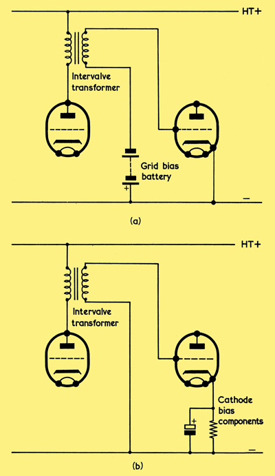
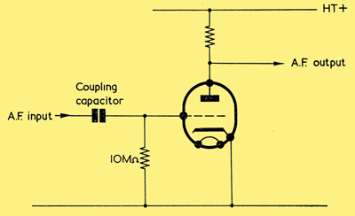
A variation on the circuit of (a) is shown below. In this instance, no direct current flows through the primary of the transformer, with the result that it can be made up in miniature form with a core of small, high permeability, laminations. These may be interleaved, as there is now no direct anode current in the primary. The alternating audio frequency voltage at the anode appears across the primary by way of the coupling capacitor, which will have a value which presents a low reactance over the audio frequencies. The only advantage offered by the circuit, when compared with normal resistance-capacitance coupling, is that the transformer offers a step-up in signal voltage. The remaining disadvantages of transformer inter-valve coupling still apply.
An alternative method of connecting up an inter-valve transformer. In this circuit no direct current flows through the primary.
Phase Reversal
An important feature of valve amplification is that the alternating voltage appearing at the anode is 180° out of phase with that applied to the grid.
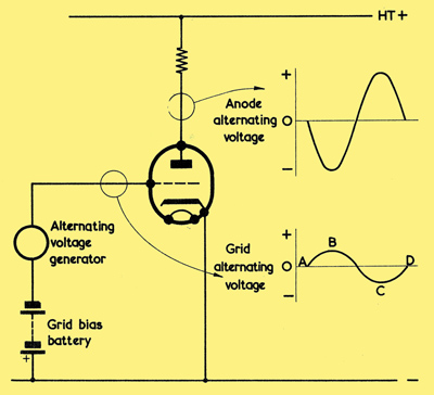
Illustrating the fact that the alternating voltage at the anode is 180° out of phase with that at the grid.
This point may be readily perceived if we examine the diagram above, in which the alternating voltage waveform at the grid is shown directly below that at the anode. At point A of the grid waveform, the alternating voltage is zero, and the grid is at the same potential as that provided by the grid bias battery. After point A the grid voltage goes positive, with the result that anode current increases. An increase in anode current causes an increase in the voltage dropped across the anode load resistor. The high tension supply voltage is fixed, and this increase in voltage across the resistor can only result in the anode going negative of the potential it previously held. The process continues as grid voltage goes more positive, with the anode voltage going correspondingly more negative. The grid voltage reaches its positive peak at point B, and the anode voltage arrives at its negative peak at the same instant. After point B the grid starts to go negative. Anode current, in consequence, starts to reduce as, also, does the voltage dropped cross the anode load resistor. The result is that the anode now starts to go positive, reaching its positive peak when the grid voltage is at its most negative peak, at point C. Finally, the grid voltage goes positive again, from point C to point D, and the anode voltage goes correspondingly negative as a result. As is evident from the diagram, the result is an alternating waveform at the anode which is 180° out of phase with that at the grid.
The Cathode Follower
It is possible to employ a valve in different circuits to the basic type we have considered up to now, wherein the input signal was applied to the grid and the output signal was obtained from the anode. It will be helpful to briefly consider these alternative modes of operation, mainly in terms of the phase relationship between input and output alternating voltages.
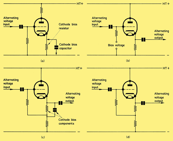
(a). A cathode bias voltage may be obtained by inserting a resistor in series with the cathode. It is necessary, however, to add a high value capacitor across the resistor to prevent the input alternating voltage appearing at the cathode
(b) The cathode follower circuit. This takes advantage of the fact that the cathode voltage 'follows' the grid voltage, whereupon an alternating voltage output becomes available at the cathode. Since the cathode resistor is now much higher in value than in (a), the cathode carries a much higher positive potential, and a suitable bias voltage is applied to the lower end of the grid resistor
(c) An alternative method of obtaining bias. The grid resistor is returned to the lower end of a standard cathode bias resistor and capacitor
(d) It is possible to obtain very similar results with the cathode bias capacitor of (c) omitted.
When, last time, we considered the cathode bias circuit, we saw that, by inserting a resistor in the cathode circuit as in (a) above, a bias voltage was applied to the cathode. We had, however, to connect a large value capacitor across the cathode resistor to enable a useful bias circuit to be obtained because, without such a capacitor, the cathode tended to go positive when the grid went positive and vice versa, therefore effectively reducing the signal voltage appearing between the grid and cathode.
It is possible to make good use of this effect by purposely omitting the high value capacitor, by increasing the value of the cathode resistor and by connecting the anode direct to the HT positive terminal. (See (b).) An alternating voltage with suitable bias is then applied to the grid, and an output is taken from the cathode. Just as occurred with the cathode bias circuit before the high value capacitor was added, the cathode will go positive when the grid goes positive and negative when the grid goes negative. In other words an alternating voltage will appear at the cathode and this will be in phase with the alternating voltage at the grid. An output for a further stage may then be obtained via a capacitor, as shown. The amplitude of the alternating voltage at the cathode in (b) will be greater than occurred in the previous cathode bias instance, because we have increased the value of the cathode resistor. Nevertheless, however much we increase the value of this resistor, the alternating voltage at the cathode will always be less than the alternating voltage at the grid and can never become equal to it. With a practical circuit, the amplitude at the cathode will be of the order of 0.9 times the amplitude at the grid. Despite the fact that a circuit of this type offers no voltage amplification it is still very useful for some applications.
A source of grid bias voltage was employed in (b), but an alternative method of obtaining bias is shown in (c). In this case we fit a standard cathode bias resistor and capacitor, the grid resistor being connected to the lower end of these two components. Very similar results (together with a saving of a component) will be given by deleting the capacitor, as in (d). (The removal of the capacitor may even be beneficial as its inclusion in the circuit results in the cathode having different AC and DC loads, these being particularly at variance if the lower cathode resistor is not high in value compared with the upper cathode bias resistor.) The signal input to the grid may be obtained via a capacitor.
A valve employed in the circuits of (b), (c) and (d) is described as a cathode follower. The name is derived from the fact that the voltage on the cathode 'follows' that on the grid.
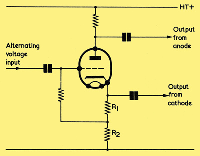
Combining the normal amplifier circuit and the cathode follower to obtain a phase splitter circuit.
An interesting adaptation of the normal valve amplifier and the cathode follower circuit is shown above. In this diagram the alternating voltage at the cathode is in phase with the input alternating voltage at the grid, whilst the alternating voltage at the anode is 180° out of phase with the alternating voltage at the grid. If the resistors in the anode and cathode circuits are made equal in value (the cathode resistor consists of R2 plus R1) the out of phase alternating voltages at anode and cathode become equal in amplitude. Equal voltage amplitudes are bound to appear under these circumstances because the same current (the anode current of the valve) flows through both the anode and cathode resistors. In the circuit the valve is described as a phase splitter.
The Grounded Grid Circuit
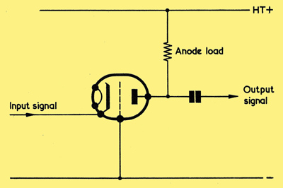
The grounded grid amplifier. For simplicity, bias arrangements are not shown. In practice they would ensure that the grid is held negative of the cathode, as with the other amplifier circuits.
Occasionally, a valve may be connected in the manner shown in the diagram above. In this case the input signal is applied to the cathode instead of the grid. However, the alternating voltage still appears between cathode and grid, and so an amplified version appears at the anode and may be taken off via a capacitor. Since the cathode going positive has the same effect on the valves electron stream as the grid going negative, the phase relationship between input and output is opposite from that given below - as before.
Illustrating the fact that the alternating voltage at the anode is 180° out of phase with that at the grid.
When, as seen below, the cathode goes positive so also does the anode, and the output alternating voltage is in phase with the input alternating voltage.
The grounded grid circuit is sometimes described as an earthed grid amplifier, the term deriving from the fact that the grid is at 'earth potential' (ie, so far as input and output alternating voltages are concerned, the grid has a fixed reference potential which does not change). It is much more common, however, to describe the circuit as a grounded grid amplifier, the alliterative form deriving from the American term 'ground', which is synonymous here with 'earth'.
Grid Current Bias
When, in earlier articles, we dealt with the diode we saw that this exhibits a phenomenon which is usually referred to as 'contact potential'. As was explained in the previous article, contact potential in a diode results in the same effect as would be given by a small internal EMF having a polarity such that anode current still flows when the anode voltage is zero. Anode current only falls to zero when the anode is made slightly negative to counteract the contact potential. The fact that a negative anode voltage results in zero anode current infers that the anode voltage has then become equal to the contact potential and that the anode would therefore, in the absence of external connections, exhibit a potential which is negative of the cathode. This assumption is, in fact, true and it may be demonstrated quite readily in practice by connecting a high resistance voltmeter across the anode and cathode of an indirectly heated diode whose cathode is at emitting temperature. The voltmeter will show that the anode is negative of the cathode, the actual voltage indicated ranging from some 0.1 to 0.6 Volts according to the diode type and the resistance of the voltmeter.
In a triode the grid and cathode form an effective diode, with the grid functioning as the anode. Because of this, the grid may assume a contact potential in just the same way as does the anode of a diode. The presence of this contact potential may be similarly checked with the aid of a high resistance voltmeter. The contact potential makes it possible to operate some triodes intended for audio voltage amplification in the circuit shown above.
At first sight it would appear that the triode is operated at zero bias, but it is, in practice, biased by the contact potential on its grid. To ensure that the contact potential remains sufficiently high it is necessary to give the grid resistor a large value, a typical figure being 10MΩ as opposed to the 250kΩ to 1MΩ which is normal with triodes using the bias circuits we have previously considered. The triode in this case remains biased by the contact potential for small signal inputs. Since the contact potential causes the grid to be negative of cathode a small current flows through the grid resistor. This is very low in value, being much less than 1μA.
The current in the grid resistor is modified by the input audio voltage, and if the latter is made sufficiently high in amplitude the positive peaks of the signal may cause positive grid current to flow, whereupon the grid acts in the same manner as the anode of a rectifier diode.
More Complex Valves
The circuits we have discussed this month have been demonstrated with triodes, but it should be pointed out that they can incorporate valves having more complex electrode structures than has the triode. Operation with such valves still follows the same basic principles as those described.
|