|
Valve Characteristics and Constants
Apart from the fact that we looked at the IaVg characteristic curve of the triode previously we have not yet discussed in detail the characteristics and constants of the triode. There are three important constants, and they provide a measure of the valves capabilities. As we shall see later, these constants also apply to amplifying valves having more complicated electrode structures than has the triode, but we shall discuss them in terms of the triode only at this stage. Triode characteristics and constants were not dealt with immediately after we introduced the triode valve because the writer feels that it is more helpful for the beginner to gain an understanding of simple applications and circuits first. It is easier to grasp the purpose of valve characteristics and constants after a basic knowledge of the manner in which the valve is to be used has already been acquired. It may be added that a valve constant is a figure which represents a particular attribute of the valve. The two constants we shall discuss this month are closely connected with sets of curves which illustrate the valves characteristics, and the sets of curves will be dealt with at the same time.
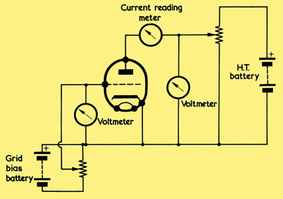
A circuit which allows the characteristics of a triode to be found. Sources of direct voltage other than batteries may, of course, be employed.
The characteristics and constants we shall now consider may all be found by means of the circuit shown above. This is similar in principle to the circuit, which we employed for obtaining (anode current-grid voltage) curves, with the exception that we now have a variable anode voltage provided by a potentiometer, and the grid voltage available cannot go positive of the cathode. As we saw in the previous article, the grid is not normally allowed to go positive of the cathode in practical applications and so characteristics are not given for positive grid voltages. The circuit given enables us to vary both the anode voltage and the grid voltage, and to measure the anode current which flows.
Mutual Conductance
Since we have already examined the IaVg curve, this provides a useful starting point for the first constant which we shall consider.
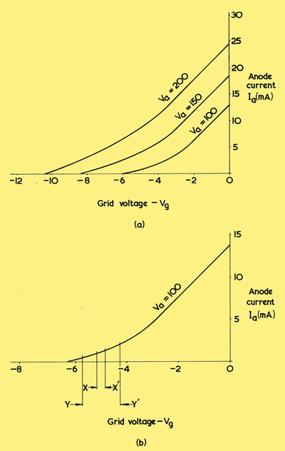
(a) Typical IaVg curves for a voltage amplifier triode
(b) Measurements of mutual conductance at a curved section of the IaVg characteristic may give different results according to the magnitude of the change in grid voltage.
(a) shows the IaVg curves for a typical voltage amplifier triode at anode voltages of 100, 150 and 200. These curves tell us that, as grid voltage goes more positive, the anode current increases. They also tell us, obviously enough, that a change in grid voltage causes a corresponding change in anode current.
The latter attribute is defined by the first constant to be discussed, this being mutual conductance. The mutual conductance of a valve is the ratio of change in anode current to change in grid voltage, the anode voltage remaining constant. Mutual conductance is expressed in milli-amperes per volt. If, at a constant anode voltage, we change the grid voltage of a triode by 1 Volt and find that this causes the anode current to change by 2 mA, then the triode has a mutual conductance of 2 mA per volt. This may be abbreviated to 2 mA/Volt or 2 mA/V. It is not necessary to find the ratio by using a change in grid voltage of exactly one Volt. If we had measured the change in anode current for a change in grid voltage of 0.25 Volt, and found it to be 0.5 mA, then the mutual conductance (which is the ratio of change of anode current to change of grid voltage) would have been 0.5/0.25 = 2 mA per Volt, just as before.
The lower ends of the curves (a) are noticeably curved and we would find that if, on the Va = 100 curve for instance, we attempted to find the mutual conductance by measuring the change in anode voltage for a change in grid voltage between X and X1 in (b), we would get a different answer than we would for a grid voltage change between Y and Y1. This is entirely due to the pronounced curvature at these points. Normally, mutual conductance measurements are taken at the straighter, or more linear, parts of the IaVg curve where the same ratio is more likely to result for both large and small changes in grid voltage. If mutual conductance measurements have to be taken for a grid voltage which appears at a pronounced curved portion of the IaVg characteristic curve, it is better to use as small a grid voltage change as practicable, in order to obtain an accurate answer for the particular grid voltage concerned. In valve manufacturers literature, mutual conductance is normally quoted for specific values of anode voltage and grid voltage, and these figures will almost inevitably apply to a linear part of the IaVg characteristic curve.
Mutual conductance may also be referred to as slope. This is because the mutual conductance figure defines the 'slope' of the IaVg curve. In the graph below, curve A has a steeper 'slope' than has curve B, whereupon it represents a higher mutual conductance.
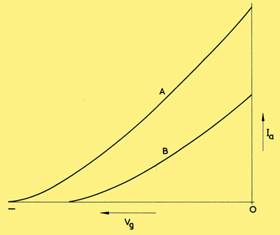
Two IaVg curves drawn on the same axes. Curve A has a steeper slope that curve B and represents a higher mutual conductance.
The abbreviation employed for mutual conductance is gm, and the definition for mutual conductance may be expressed in the following equation:-
gm = δIa/δVg (Va constant)
Non-mathematical readers should not worry about the letter δ which appears before 'Ia' and 'Vg'. In the fraction this letter merely signifies that the denominator (δVg) is 'change in Vg and that the numerator (δIa) is 'corresponding change in Ia'.
To quote our previous example, if the change in grid voltage (δVg) is 1 Volt and the corresponding change in anode current (δIa) is 2 mA, then the equation tells us that gm = 2/1 = 2 mA per Volt. We would get the same answer with the grid voltage change of 0.25 Volts and the corresponding anode current change of 0.5 mA which was also mentioned. The term Va appearing in the equation stands, of course, for anode voltage.
In American terminology, mutual conductance is usually referred to as trans-conductance, or grid-plate trans-conductance (the term plate being employed instead of anode just as vacuum-tube is used in place of valve). Mutual conductance is also expressed in micro-mhos, instead of in mA per volt. To understand why this unit is employed we have to go back to our basic electrical quantities. Resistance is measured in ohms, and is equal to I/E where E is the applied EMF in Volts and I is the current, in Amps, which flows. Conductance is the reciprocal of resistance, and the basic unit of conductance is the mho (the word 'ohm' spelt backwards). Thus, conductance (in mhos) = 1/(resistance in Ohms). If a circuit component has a resistance (in Ohms). resistance of 3 Ω, it has a conductance of 1/3 mho.
Since conductance is the reciprocal of resistance, it is equal to I/E . Now, our mutual conductance is δIa/δVg , which is also a current divided by a voltage, and we may see, in consequence, how the term mutual conductance derives. Mutual means conjointly shared and so mutual conductance refers to a conductance which is conjointly shared between grid and anode. A mutual conductance of 2 mA per volt may be expressed, in terms of Amps and Volts, as 0.002 Amps per Volt or 0.002/1 mhos. It is more convenient to use the micro-mho (one millionth part of a mho) than the mho, whereupon our mutual conductance becomes 0.002/1 x 1,000,000 = 2,000 micro-mhos. It may be seen from this that, to express mutual conductance in micro-mhos, it is only necessary to multiply the mA per Volt figure by 1,000. Similarly, a mutual conductance figure in micro-mhos may be changed to mA per volt by dividing by 1,000.
A final point is that a set of IaVg curves, such as those shown in (a), are referred to as the mutual characteristics of the valve concerned. They may also be described as the transfer characteristics.
Anode AC Resistance
The second important constant we shall consider is the AC resistance, or anode AC resistance, of a triode, This is not a new concept to us because we have examined the AC resistance of the diode. We saw that the resistance to an alternating current offered by a diode depends upon the slope of the IaVa characteristic curve. The AC resistance offered was demonstrated by considering the alternating current which flowed at a known alternating voltage, and it was pointed out that this AC resistance had no connection with the DC resistance of the diode.
The same applies to the triode, and we may define anode AC resistance as the ratio of change in anode voltage to the corresponding change in anode current, grid voltage remaining constant. Anode AC resistance is expressed in Ohms. As was pointed out when we dealt with the diode, the term 'anode AC resistance' is abbreviated to ra. If a change in anode voltage of 10 Volts corresponds to a change in anode current of 2 mA, or 0.002 Amps, then the anode AC resistance in Ohms is 10/0.002 = 5,000.
We may express anode AC resistance in the form:-
ra = δVa/δIa (Vg constant).
In this equation, the letters δ carry out the same function as with the mutual conductance equation. The term 'δIa' means 'change in Ia' and the term 'δVa' means 'corresponding change in Va'. The similarity of the equation to that for resistance, R = E/I, is readily apparent.
We explained anode AC resistance with the diode by drawing its IaVa characteristic curve and we shall now do the same for the triode. However, the grid of the triode introduces a complicating factor, and it is necessary, if a full picture of the performance of the triode is to be given, to draw not one IaVa characteristic curve, but a relatively large number of curves, each corresponding to a different grid voltage. A typical example is shown in below, in which we see a 'family' of IaVa curves with grid voltage as parameter. We can find anode AC resistance at any grid voltage and anode voltage, or at any grid voltage and anode current, by checking the slope of the IaVa curve at the corresponding point. In valve manufacturers literature, anode AC resistance is normally quoted for specific values of anode voltage and grid voltage, these applying to a relatively linear section of the IaVa curve. Anode AC resistance can be looked upon in the same manner as the internal resistance of an AC generator. It may also be referred to as anode impedance or anode incremental resistance, and, in American literature, as plate resistance. A set of IaVa curves, such as those shown below, are described as the anode characteristics of the valve.
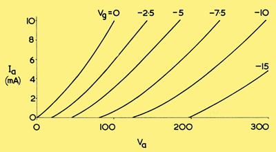
A set of IaVa curves for a typical voltage amplifier triode. Each curve corresponds to a different grid voltage.
|