|
The Miller Effect
Last time we concluded our discussion on the triode as voltage amplifier and examined some practical triodes, as are encountered in commercially manufactured audio amplifying equipment.
We now turn our attention to a further factor which has to be considered in relation to the triode, this being Miller Effect.
Inter-Electrode Capacitance
Since the electrodes of a triode valve are in fairly close proximity to each other, it follows that a capacitance exists between them. Capacitances also exist between the leads and pins connecting to the electrodes, these capacitances being in parallel with the capacitances existing between the associated electrodes themselves.
In conventional voltage amplifier triodes the inter-electrode capacitances are quite small and are normally less than some 2.5 pF. These small capacitances have negligible effect on circuit operation in some applications, but in others they are of importance and have to be taken into account. Inter-electrode capacitances are identified by the small letter 'c' followed by suffix letters designating the electrodes concerned. The small 'c', instead of a capital letter, is used because the capacitance is inside the valve. Thus, the expression ca-g represents the capacitance between anode and grid, cg-k the capacitance between grid and cathode and ca-k the capacitance between anode and cathode. Also of importance is ck-h, which represents the capacitance between cathode and heater. With directly heated triodes, inter-electrode capacitances to the filament are referred to as cg-f and ca-f the letter 'f' (for filament) replacing the letter 'k' (for cathode). More complicated expressions for inter-electrode capacitances may also be encountered, two typical examples being cg-h+k and cg-all. The first of these expressions refers to the capacitance given with the grid as one 'plate' of the effective capacitor, and the heater and cathode joined together as the other. The second (which is usually applied to valves having more complicated electrode structures than the triode) refers to the capacitance between the grid as one 'plate' and all the remaining electrodes joined together as the other. Modern practice has introduced two further expressions, these being cin and cout. The expression cin stands for the capacitance between the input electrode (the grid) and all other electrodes except the output electrode (the anode) joined together. The expression cout refers to the capacitance between the output electrode (the anode) and all other electrodes except the input electrode (the grid) joined together.
The expressions for inter-electrode capacitance just given will be found in the specifications for their products which are issued by the valve manufacturers. It may be noted, in passing, that the capacitance figures quoted by manufacturers normally apply, unless otherwise stated, to the valve when it is cold (i.e. no heater or filament supply applied).
To give an idea of the inter-electrode capacitances offered by practical valves the cin of either triode of the double-triode ECC82 is specified as 1.8 pF and the ca-g as 1.5 pF. The cout of one of the triodes is specified as 0.370 pF and the cout of the other triode as 0.250 pF.
Miller Effect
When a triode is employed as a voltage amplifier an internal action takes place within the valve which modifies the effective capacitance between the grid and the anode, and this action we shall next consider.
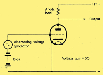
Illustrating Miller Effect in a voltage amplifier triode. The input capacitance here is (50 + 1) ca-g + cg-k
Above we have a triode voltage amplifier to whose grid is connected a generator. The valve is biased in normal fashion by means of a battery which is assumed to have zero internal impedance, and we shall state, for simplicity in the explanation, that the triode offers a voltage gain of 50.
The function of the generator is to apply an alternating voltage to the grid. Assuming that there is no grid current and that all insulation is perfect, we could then, at first inspection, make the assumption that the generator has to provide no current at all. But such an assumption is not, in practice, true, because the alternating voltage generator is connected to a component having capacitance. Part of this capacitance is given by cg-k, the capacitance between grid and cathode, and current is required from the generator to ensure that the cg-k charges and discharges in sympathy with the applied alternating voltage. The cg-k can be looked upon as a physical capacitor, the upper 'plate' being the grid and the lower 'plate' the cathode. Obviously, the upper 'plate' connects directly to one terminal of the generator, whilst the lower 'plate' connects directly (via the bias battery which is assumed to have zero internal impedance) to the other terminal of the generator.
Things are not so straightforward when we come to consider the next inter-electrode capacitance, that between anode and grid. Again, we can think in terms of a physical capacitor, with the grid being the lower 'plate' and the anode being the upper 'plate'. In this case, however, whilst the lower 'plate' of the ca-g connects directly to one terminal of the generator, the upper 'plate' is in a circuit which causes it to have a constantly changing potential.
Let us now examine what happens during a cycle when the alternating voltage generator is causing the grid to go positive. The valve has a voltage gain of 50, and the signal at the anode is 180° out of phase with that at the grid. So, for every Volt that the grid goes positive, the anode goes negative by 50 Volts. Had the anode voltage remained constant the current in the anode-grid circuit would have been that needed to charge and discharge the ca-g on its own; but what happens now is that, when we make the lower 'plate' of the ca-g positive by 1 Volt the upper 'plate' counteracts this by going negative by 50 Volts. If we make the lower 'plate' negative by,1 Volt the upper 'plate' counteracts this by going positive by 50 Volts. The generator has, therefore, to provide charge and discharge currents which will overcome this 50-fold counteracting effect, and the circuit functions as though we were trying to charge and discharge a capacitor having 50 times the actual value of the ca-g. This is, indeed, the case, because a measure of capacitance in a capacitor is given by the current which flows when an alternating voltage is applied to it. So far as the generator is concerned, the result is the same as would be given if it applied its output to a capacitor having 50 times the value of the actual ca-g.
We have, in the last paragraph, considered the apparent capacitance which is 50 times the ca-g, but we must not forget the physical capacitance given by the ca-g itself. We have found that the generator has to provide charge and discharge currents to overcome the 50-fold counteracting voltage at the anode, but we must also remember that the generator has to provide the charge and discharge currents which are needed to change the grid potential in the first place. These charge and discharge currents are those resulting from the ca-g itself. So the overall capacitance, apparent and real, becomes 50 times the ca-g plus the ca-g itself, or (50+1) times the ca-g.
Another way of looking at the effect just described is to assume initially that the alternating voltage generator is providing zero output, and that the anode swings negative and positive by, say, 50 volts peak. It is obvious that charge and discharge currents due to the ca-g will flow in the generator. We next cause the generator to provide the output of 1 Volt peak which corresponds to the 50 Volts at the anode, whereupon the charge and discharge currents are increased by those needed to swing the grid through its 1 Volt peak signal. The total charge and discharge currents are then (50+1) times the currents which would flow due to the ca-g alone (or which would flow if the anode potential was fixed instead of varying). Had the voltage gain of the valve in the diagram been 25, the effective anode-grid, capacitance, apparent plus real, would have been (25+1) times the ca-g. Had the gain been 40, the effective anode- grid capacitance would ,have been (40+1) times the ca-g. It follows that, if we call the voltage gain A, the effective anode-grid capacitance becomes (A+1) times ca-g.
We can now see that the total capacitance for which the generator has to provide charge and discharge currents is (A +1) times the ca-g, to which must be added the ca-g, and any further capacitances which exist between the grid and other electrodes which are at HT negative potential so far as AC is concerned. With a triode the latter may usually be ignored whereupon, for most purposes, it becomes adequate to assume that the capacitance for which the generator has to provide charge and discharge currents is (A+1) ca-g + cg-k. This capacitance is referred to as the input capacitance of the valve under the working conditions applicable. This term should not be confused with the cin symbol mentioned earlier. The cin figure is a valve specification and is the result of a capacitance measurement taken when the appropriate valve is not operating. The effect just described, in which the ca-g is apparently multiplied by (A + 1) is referred to as Miller Effect.
Miller Effect can result in relatively high input capacitances for voltage amplifier triodes. The gain of 50 chosen for our explanation is not unusually high by practical standards and is, indeed, the figure we found last month when we examined one triode of the ECC83 in a voltage amplifier circuit employing an HT voltage of 250 and an anode load resistor of 100kΩ. The ca-g of either triode of an ECC83 is quoted, in the valve manufacturers literature, as 1.6 pF. With a gain of 50, the input capacitance due to Miller Effect then becomes (50 + 1) times 1.6 pF or 81.6 pF. This corresponds to a reactance of approximately 200kΩ at 10 Hz. If the ECC83 triode under consideration were employed in an audio circuit with conventional resistance-capacitance coupling to the grid, this input reactance could result in a loss in overall circuit gain at the higher audio frequencies. Such a loss would be permissible in, say, a low-cost radio receiver, but it would have to be taken into account in the design of an amplifier intended for high fidelity reproduction.
|