|
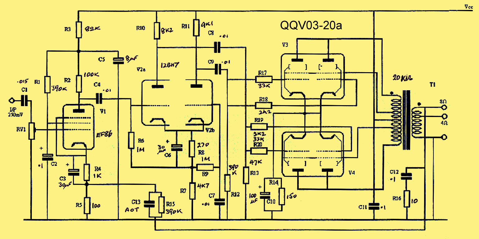
The circuit of the QQV03-20A valve amplifier.
The Circuit
The circuit uses a standard configuration of low noise voltage amplifier, phase splitter and push-pull output stage. Valves used: EF86, 12BH7 & QQV03-20A
The QQV03-20A is a VHF double beam tetrode designed for use as a Class C RF power amplifier or as a Class B push-pull modulator and as such is built to have the grid driven positive. When used in Class A or Class AB1 the sound produced is excellent but the power is quite small. The author has built a Class A push-pull amplifier that uses a single QQV03-20A in the output stage preceded by an ECC83 phase splitter and listening tests have been most favourable. However, the power is only three to four Watts
The QQV03-20A will be seen to have a screen grid (g2) that is common to both sections and so using this valve as a single 20 Watt anode dissipation beam tetrode makes sense as the ultra-linear transformer connection can be used to reduce distortion.
The QQV03-20A, QQV03-25, QQV06-40A and QQV07-50 European pattern double beam tetrodes with internal neutralisation all have the same pin connections and trying them in this basic circuit should produce interesting results.
More details are required and the writer hopes to build this design and present findings.
How to use the QQV07-50
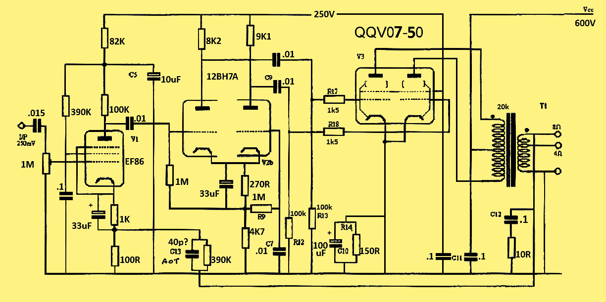
The circuit of the QQV07-50A valve amplifier.
Robert Coleman has re-worked the original circuit to use the 25 Watt dissipation QQV07-50 VHF double tetrodes. To make good use of these higher dissipation valves the HT has been increased to 600 Volts whilst keeping 250 Volt HT for the earlier stages.
Thanks to Martin Billington for allowing the QQV03-20A circuit to be reproduced here.
|