|
Innovation at the End of the Valve Era
The development of the Nuvistor in the late-1950s was probably the last major innovation in receiving valve technology, coming as it did towards the end of the era of thermionic device domination. Transistors at that time weren't the full answer to all problems in electronics, and so valves still had a lot to offer. The Nuvistor is often regarded as a last desperate effort by valve manufacturers to stem the flow of 'transistorisation' which was becoming a torrent by this time. Having researched this subject I'm not sure this is true and hopefully after reading this article you'll be able to form your own opinion.
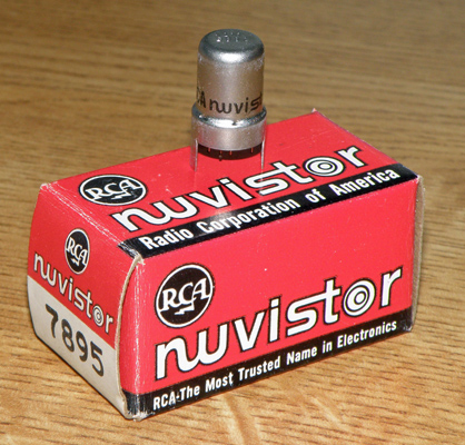
RCA's special box with the Nuvistor logo on it. The device perched on the box is a 7895 triode. You may just be able to see the Nuvistor logo on the valve itself.
Introduction of the Nuvistor
RCA announced the first Nuvistor triode valve, the 7586, in 1959. Modern folk law has the initial intended application as TV VHF/UHF tuners, from where they were finally displaced by transistors in the early 1970s. Further triodes, such as the 6CW4 (which is probably the most well-known Nuvistor) and a tetrode or two followed over the next few years.
From the start RCA clearly had applications in mind beyond TV tuners. In a 1959 RCA advert the company claimed:
RCA Electronics introduces the tube of tomorrow
Called the Nuvistor, this thimble-sized tube is likely to start a revolution in electronics. RCA engineers scrapped old ideas - took a fresh look at tube design. The result will be tubes that are far smaller, perform more efficiently, use less power, can take more punishment, are more reliable. Developmental models now being tried out by designers will have a profound effect on the size, appearance, and performance of electronic equipment for entertainment, communications, defence, and industry in the future. It is another example of the way RCA is constantly advancing in electronics.
The accompanying photograph showed a Nuvistor 'being born', breaking out of an egg.
The Nuvistor Brand
The 'Nuvistor' name was intended to evoke similarities to the words 'new' and 'transistor', presumably to help overcome bias against the use of 'old fashioned' valve technology. In adverts and application data the word 'Nuvistor' was printed in a unique font, giving the impression of a Nuvistor logo, and this can be seen in the Geloso advert later on in the article. RCA even shipped Nuvistors in a special box (at least in the early days - See picture above) with the Nuvistor logo on it, rather than the generic 'RCA Electron Tube' printed on most of their boxes.
RCA coined the word 'Nuvistorization', this being the process of designing Nuvistors into new equipment. RCA wrote: 'Nuvistorization has been the answer to many critical design problems: it may be the answer to yours'
Nuvistor Types
Nuvistors were released as triodes and tetrodes (I use the plural here, which is just about valid: so far I have only managed to find two US-produced tetrodes, the 7587 and the 8380), in their own unique and compact metal envelope and ceramic base formats. In Table 1 I've tried to summarise the significant data on all the Nuvistor types I've tracked down. You may have already heard of the 6CW4 triode which was used in many amateur VHF and UHF amplifier and converter designs during the 1960s. There may be ones I've missed, especially 'special quality' ones designed for rugged industrial applications. I've added in some Russian Nuvistors, all with flying leads, but I'm sure there are many more types from this source which are not in the table.
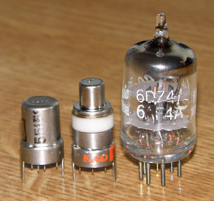
A Siemens 8056 Nuvistor triode and an RCA 7587 tetrode, alongside a B7G-based 6DZ4 / 6AF4A UHF oscillator triode to show the comparative size of these formats.
Above is a photo of a Siemens 8056 triode and an RCA 7587 tetrode, alongside a 6DZ4 / 6AF4A B7G-based UHF oscillator triode valve which was typical of the valves the Nuvistors were in competition with, so you can compare them. As you can see the Nuvistor is considerably smaller than the 6AF4A.
The image below shows a close-up of an 'HP' 6CW4 triode and the RCA 7587 tetrode side-by-side. Both valves have been plugged into their sockets, which don't add too much to the overall size. I would think that the 'HP' valve was thus labelled for use in Hewlett-Packard test-gear but was not manufactured by Hewlett-Packard itself. Note how the valves' part numbers are deeply stamped into the tops of the metal shells - no chance of it rubbing off, which is definitely a problem with glass-enclosed valves!
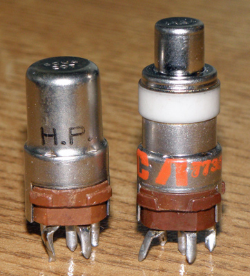
Close-up of an 'HP' 6CW4 triode and the RCA 7587 tetrode plugged into their sockets. I've also seen a socket suitable for PCB mounting, and some Nuvistor triodes with gold-plated cases. I would think that the 'HP' valve was thus labelled for use in Hewlett-Packard test-gear but was almost certainly not manufactured by H-P itself.
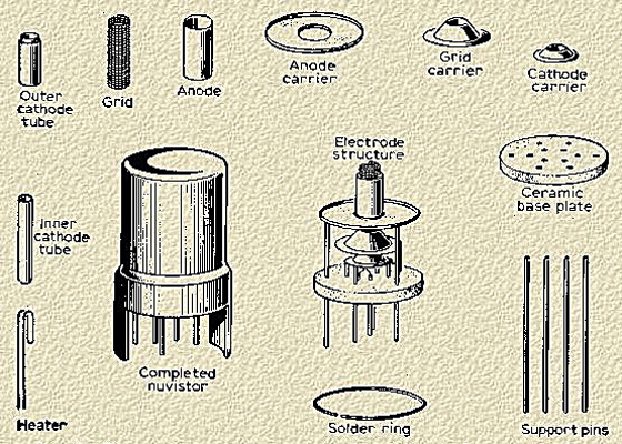
Metal Case and Twelvar Base
A special case design was developed for these new valves, resulting in small size and very good high frequency performance, which are clearly good news for the RF stages of TV sets, but also have other useful attributes for more onerous applications. The standard triode MT4 metal shell case is shaped like an upside-down thimble, but at about 20mm high and 11mm in diameter is somewhat smaller. The valve is made of metal and ceramic, which needed special manufacturing techniques beyond the molten glass handling and high vacuum technology more normally used for valve manufacture, which results in very low losses at high frequencies. There is no glass envelope to be evacuated towards the end of the manufacturing process: the case was assembled by remote control in a vacuum chamber and the ceramic base sealed to the metal case. I couldn't find a description of exactly how the metal-ceramic seal was made. This must have been quite tricky as it had to preserve the vacuum as the valve's case warms up and cools down in service.
The tetrode case (also used for some triodes) has an anode cap, insulated from the metal case by a ceramic ring. The case itself is often connected to the grid of the valve, making it relatively easy to get a good ground connection in grounded-grid circuits.
Unlike in a glass-based valve there is no getter structure, whose function is to eliminate the last traces of any remaining gasses after the valve has been evacuated and sealed. I can only conclude that the quality of the vacuum created inside the Nuvistor was very good indeed, without the need for a getter-type process step.
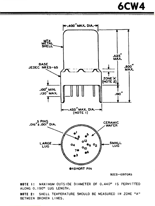
RCA's data for the 6CW4 showing the physical construction and dimensions. The way the 'long' and 'short' pins protrude through the ceramic base wafer can be seen. Click image for full data-sheet
The diagram above shows an extract from RCA's data-sheet for the 6CW4 showing the physical construction and dimensions. Twelve pins (hence the 'Twelvar' name of the base) protrude through the ceramic base, some of which are 'long' and form the connections to the heater, cathode, grid, anode and screen grid (if fitted) electrodes, and some are 'short' and barely protrude. These 'short' pins support the internal structure, along with the 'long' ones. See below for how these pins look on a 6CW4. The pins are integral with the internal structure of the valve, and do not have welded connections onto internal leads connecting to the electrodes, as is the case with most previous valve designs. These direct connections help reduce lead inductance and hence improve high frequency performance.
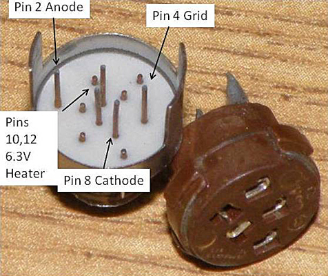
I've labelled up the pins on the base of a Nuvistor triode, alongside its socket. You can see the 'short' pins which barely protrude through the ceramic base and which support the internal structure of the valve, and the 'long' pins that connect to the socket.
Two lugs ('large' and 'small') adjacent to pins 2 and 4 locate the valve in its socket, which is shown alongside. All the pins have a diameter of 0.4mm and to prevent them from being accidentally bent the metal case extends down beyond the ceramic base, and the lugs project beyond the pins, thereby protecting the pins from most handling abuse. The valve plugs in and out of the socket relatively easily, which contrasts with how difficult these operations are with 'acorn' valves, an earlier high frequency valve technology [1] 'Acorn Antiques - High Frequency Valves Ready for War' by Stef Niewiadomski. Radio Bygones Issue No.128 (Christmas 2010) and No.129 (February/March 2011). I presume that for high reliability applications there must have been an arrangement for holding the valve firmly in the socket in the face of vibration and shock.
Nuvistor Internals

Inside view of a 6CW4, after a narrow ring of the case had been ground away so that it could be lifted clear. I may have bent the anode carrier slightly when removing the case.
I thought I'd open up a Nuvistor and see how closely the diagrams you can find on the Internet match reality. I ground away the metal around the circumference of the case of an RCA 6CW4 close to the base and you can see the 'insides' above.
Mullard's exploded view of the Nuvistor triode and its component parts. Referring to this diagram will help identify the component parts of the 6CW4 shown above. The ceramic base is about 10mm in diameter.
Mullard's diagram of the internal structure of a Nuvistor helps work out which parts of the 'de-capped' 6CW4 do what. All the electrodes are supported by the long and short pins. Note that there are no mica spacers used to support and separate internal structures, as in 'normal' valves. Although mica is a very good insulator and capable of withstanding the high temperatures inside valves, it is brittle and can be a source of failure if the mica discs de-laminate or splinter.
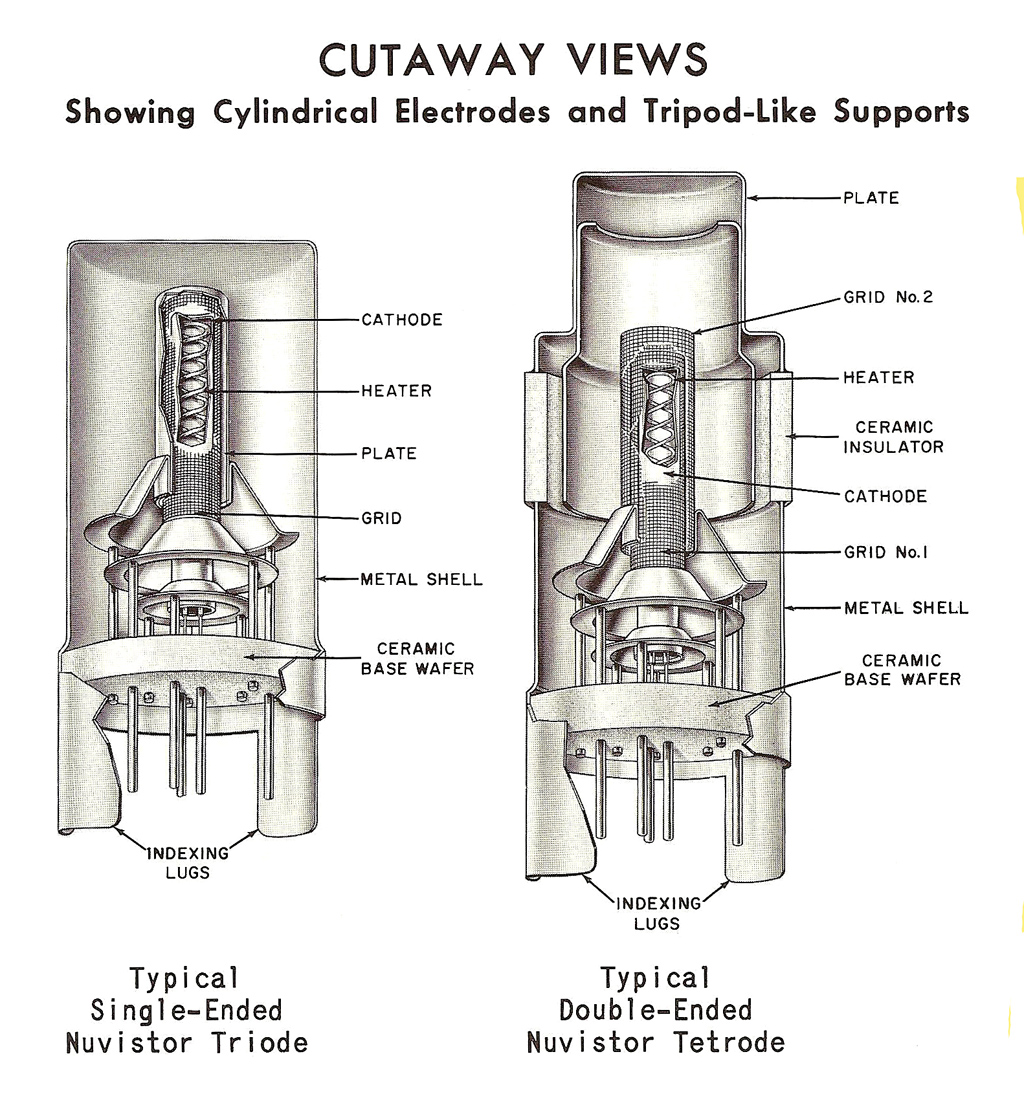
Cut-away view of a Nuvistor triode (left), and a tetrode (right) with a top cap connection to the anode, as typical of the 7587. This picture shows very well the coaxial nature of the heater, cathode, grid and anode electrodes.
The image above shows cutaway views (from RCA's own data [2] 'RCA Nuvistor Tubes for Sonobuoy and other Expendable Equipment'. Published by RCA in September 1963.) of a triode and a tetrode Nuvistor with an anode ('plate' in US-speak) top-cap, similar to an 8058. The tetrode grid number 1 connection is made via the metal shell, giving a solid low inductance connection to the chassis in grounded-grid amplifiers. These views show the cylindrical electrodes very well and the supporting structure of the pins projecting directly through the ceramic base wafer.
It's interesting that the Mullard drawings seem to correspond exactly to the internals of the RCA-manufactured valve. One explanation is that RCA 'transferred' the design and manufacturing technology to Mullard under some mutually beneficial arrangement, as happened with many other valve designs. It may even be the case, as postulated by John W Stokes [3] '70 Years of Radio Tubes and Valves' by John W Stokes. Published in 1982 by The Vestal Press Ltd, New York., that RCA was the sole manufacturer (in the Western world at least) of Nuvistors and they allowed Mullard, Siemens and others in Europe, and other valve manufacturers in the US, to re-sell RCA-manufactured Nuvistors, having stamped them with their own logos. If you search for 'nuvistor' on eBay, you'll find many examples for sale, along with their photos. This is a useful resource for viewing many manufacturers' products: I think I can see some examples with squarer shoulders than others, so maybe the single manufacturer theory is incorrect.
Comments from readers who may have actually seen European Nuvistors being manufactured would be welcomed.
Valve Competition to the Nuvistor
By the late 1950s high frequency valve technology was well advanced and had already passed the 1GHz operating frequency point. Several VHF/UHF triodes, such as the 6Q4 (EC80), the A2521 (made by the GEC MO Valve Co.) and the 6AM4 appeared in the 9-pin all-glass B9A envelope. You may be used to seeing other B9A valves (for example the EL84) in quite long envelopes, but these UHF valves were typically only 1½ inches long, which was all that was needed to accommodate the small anode needed to dissipate the relatively low amount of heat generated in these small signal valves. The rationale behind using a 9-pin envelope was that this allowed five pins (usually pins 1, 3, 4, 6, and 9, evenly spaced around the base, and sometimes gold plated in later versions) to be used to bring out the grid connection, keeping a very short and therefore low inductance connection to ground for this critical path in grounded-grid applications.
Brimar described its 6AM4 (introduced in 1954) as being 'for grounded-grid amplifier or mixer use in the frequency range 470 to 890MHz'. The valve was compact, at 37mm tall excluding pins, and its 6.3V heater consumed 225mA, that is a heater power of about 1.42W. The valve was also given the service code CV5073. Also coming in at the same heater power were the 6AF4 (also known as the EC94 and CV5036) B7G 'UHF oscillator triode for TV sets', and the 6AN4 (CV3989) 'UHF high-mu triode for TV sets', both in the smaller B7G envelopes. The 6AF4A has an even shorter envelope than the 6AF4.
The B9A-based valves tended to have higher heater currents, and therefore dissipated higher power. For example the A2521's heater consumed 2.93W, and the 6Q4 came in at 3.5W. Another competing valve was the E88CC (which in theory should have been numbered as the ECC88, but the special quality of the valve was indicated in the Mullard coding system by the numbers being presented immediately after the 'E') twin triode (service code CV10320), again in a B9A envelope, and with a 6.3V heater taking 300mA, which gives a heater power of 2.93W.
One of the few VHF/UHF pentodes, the Mullard E180F, was also produced in the B9A format. Mullard describe the valve as a high-slope RF pentode primarily intended for use in wideband amplifiers in telephone carrier systems, radar equipment and measuring equipment. The valve was equivalent to the 6688 and the CV3998. In amateur service the E180F was mainly used in the transmit, rather than the receive, path of VHF equipment.
For good UHF performance the Nuvistor was designed to have low inter-electrode capacitance, especially the grid to anode capacitance; high transconductance; a high amplification factor; and a low noise factor. The small physical size of the Nuvistor case meant that the heater power had to be kept as low as possible, but this diminutive size also meant that the cathode was small and so less power was needed to coax it to emit the electrons needed for operation. Heater power of less than 1W was achieved for most Nuvistors, and with typical anode voltages in the range 70-100V (and even lower in some specialised applications), HT power consumption could also be kept low.
This low heater power implies a simpler (and cheaper) method of heater supply generation and less heat needed to be removed from the equipment's enclosure. All good trends, and counter-acting to some extent the big advantage of a transistor, that is, of needing no heater power at all.
Use in the Audio Studio
One famous audio application of the Nuvistor was in the mid-1960s Ampex MR-70, a costly studio-grade 1-inch 4-track tape recorder whose entire electronics section was based on 7895 triodes and push-pull pairs of 7587 tetrodes. The schematic of this tape recorder can be seen at [4] The schematic of the Ampex MR-70 tape recorder..
Another audio application of Nuvistors was in studio grade microphones in the mid-1960s, the AKG/Norelco C12a being a good example, which employed the 7586 triode. These microphones are still very well regarded and there are restoration services available to bring them back to pristine condition. Complete power supplies, replacement capacitors, and the 7586 valves for these microphones still come up for sale on eBay occasionally.
In the famous Neumann U47 studio condenser microphone, the Nuvistor was used as a replacement for the obsolete Telefunken VF-14 valve. The VF-14 was used in the war in portable field radios, and was not manufactured after the war, and suitable valves were selected from what limited stocks still existed. This needed considerable modifications to the microphone and its accompanying power supply, which could supply up to two microphones at the same time. This microphone was highly regarded by artists all over the world, and was used by many top recording artists such as Frank Sinatra, The Beatles, and so on. Companies still make adaptor modules for replacing the VF-14 with a 13CW4. Remarkably, I can currently see a U47 microphone, with its stand, cables and power supply on eBay for $10,999 Buy-it-now!
The 1966 U64 studio microphone was equipped with a 7586 Nuvistor from day one. The external power supply generated 6.2V DC at 135mA and 120V at 0.9mA for the valve. This solved any obsolescence issue as the 7586 was obtainable everywhere, and could easily be replaced if necessary as it was mounted in a socket.
A detailed description of the construction and mode of operation of the Neumann microphones, including the low noise built-in valve amplifier can be found at [5] 'New High-Grade Condenser Microphones parts 1-4' by F W O Baugh. Published in Wireless World February-May 1953..
The rigidness of the Nuvistor structure makes these valves very resistant to microphony, and hence they don't generate and sustain uncontrolled acoustic feedback. Along with low noise and low power this is a key reason why they have been used in microphones, and also in high-quality audio pre-amplifiers.
The RCA New Vista Colour TV Chassis
The US transitioned from black-and-white to NTSC-based colour TV between 1953 and 1968. Beginning in 1961 with RCA's CTC-11 chassis for the 'New Vista' line of color sets a Nuvistor was used as the RF amplifier in the tuner for about ten years. Its excellent VHF and UHF performance plus low noise figure made it a good choice when compared to competing valves or transistors of the day. There's no escaping the similarity between the word 'Nuvistor' and the phrase 'New Vista': since the valve appeared before the CTC-11 chassis design, we can only conclude that RCA's TV marketing men devised the play on words and made use of it in their adverts.
The tuner of an RCA CTC-11 TV set, showing the 6EA8 oscillator/mixer and 6CW4 RF amplifier valves. The 6CW4 is to the right of the chassis. Photo used by kind permission of Phil's Old Radios, Copyright 2011 Philip I Nelson, all rights reserved.
The CTC-11 used 25 'normal' valves and one 6CW4 Nuvistor. The VHF/UHF tuner contained a B9A 6EA8 and the 6CW4. The tuner of a CTC-11, showing the 6EA8 oscillator/mixer and 6CW4 RF amplifier valves, can be seen above. As well as showing the electrical components in the tuner I think this view shows the mechanical complexity of the unit. There's a description of the restoration of a 1962 CTC-11 colour TV at [6] A description of the restoration of a 1962 RCA CTC-11 colour TV..
Each generation of RCA's colour TV chassis (for example, CTC-10, CTC-9, CTC-7, etc, working backwards) used the state-of-the-art technology of the time to achieve the best possible picture quality in fringe reception areas. For example, the CTC-7 used an RCA-designed 6BC8 twin-triode in cascoded triode configuration in its VHF tuner. Some models in this range were VHF-only, and some were fitted with a UHF tuner.
1953 'previous art' of colour VHF/UHF TV tuner design used a 6BQ7A twin triode RF amplifier on VHF feeding a 1N82 'silicon crystal diode' mixer to produce the IF at 41MHz. On UHF (in the range of 480MHz-970MHz) no RF amplifier was used before the 1N82. This arrangement was described in detail in the RCA Review for September 1953 and can be seen at [7] RCA's CTC-7 chassis RF arrangement was described in detail in the RCA Review for September 1953..
Nuvistor Valves in Domestic Radios
Nuvistors were also found in some high quality broadcast radios. For example two 6CW4s were the lone valves used in Braun's 1969 high quality AM/FM radio model CE1000, along with 30 semiconductor devices. This model is still considered to be a classic and is collected by enthusiasts today.
The Trio-Kenwood model KW-1100U AM/FM receiver used a 6CW4 as the VHF RF amplifier in its all valve line-up. When I looked at its schematic [8] The schematic of the 100% valve Kenwood KW-1100U AM/FM tuner. I thought I'd spotted four more Nuvistors, numbered as 7591s, in the audio output stages, but when I looked these valves up they turned out to be octal-based audio power amplifier valves. These all-numeric valve codes can be very misleading!
The early 1960s Knight KN 310M FM-Multiplex Stereo Receiver, manufactured by the Allied Radio Corporation of Chicago, Illinois, is a good example of an early hybrid radio. When most amplifiers of the time still used valves the amplifier in this receiver was partially transistorised while still incorporating Nuvistors in the front end. In the mid-1960s the Knight range of quality receivers and amplifiers were offered as kits in the UK, by Electroniques.
Many other manufacturers, such as Sansui and Pioneer, typically used the 6CW4 in their FM tuners.
Amateur Equipment
Many professionally-built equipment for the amateur bands used Nuvistors. For example the 1962 Hallicrafters HA-6 6m (50MHz-54MHz) transverter used a 6CW4. On the receive side, the 6m band was converted down to 28MHz-30MHz (the amateur 10m band), and on the transmit side the output from a 10m transmitter was converted up to 6m and amplified to give an output power of 60W PEP on SSB, CW and FM, and 15W on AM.
The Lafayette air-band (108MHz-136MHz) receiver model HA-55A, introduced in 1964, used a 6CW4 as an RF amplifier, the rest of the set being populated with 'conventional' B9A and B7G valves. I've shown below a photo of the top chassis view of the HA-55A.
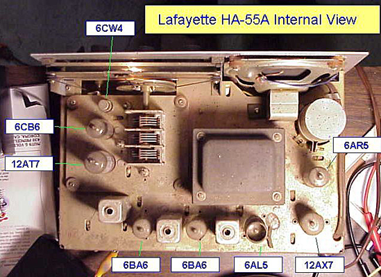
An internal view of the Lafayette HA-55A aircraft band receiver, showing the 6CW4 Nuvistor RF amplifier stage.
Nuvistors, specifically the 6CW4, seem to have become commonly available in the UK in the first half of 1963. The table below shows part of RST Valve Mail Order Co's price list, as published in the May 1963 issue of Practical Wireless. As you can see the 6CW4 was listed at 16/- : the price of that issue of Practical Wireless was 2/-, so maybe you can get a feel for how affordable the valve was. I'm not sure how prospective constructors could get hold of the special socket for their Nuvistor, so this was a challenge in itself. In the same price list the B7G-base 6C4 triode was 4/6, so there was a considerable premium to pay for Nuvistor technology. By 1975 the 6CW4 was priced at #1 in a magazine costing 30p, so it was considerably cheaper in real terms by then.
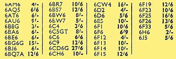
A section of RST's advert in the May 1963 issue of Practical Wireless, the first time the 6CW4 appeared for sale to the general public in the UK, priced at 16/-. Compare this with the 3/6 being charged for the B7G 6C4 triode. The 6F12 was Mazda's version of the ubiquitous 'EF91' pentode.
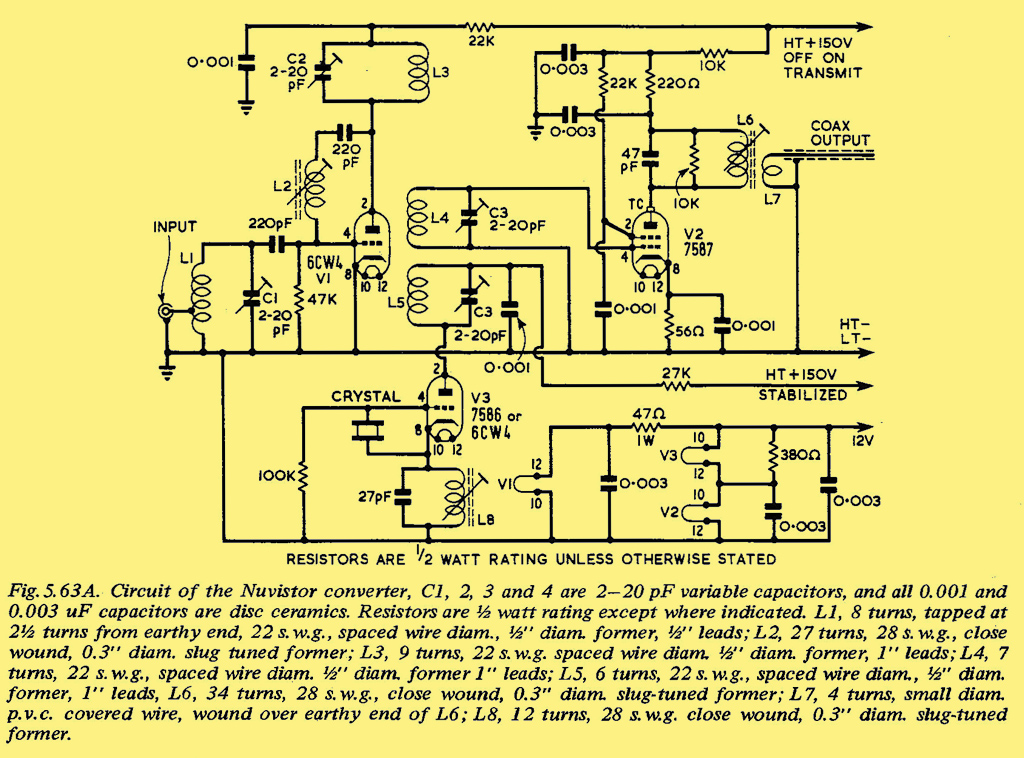
The schematic of the 100% Nuvistor-based 70MHz converter in the 1969 edition of the RSGB's VHF-UHF Manual.
The diagram above shows the schematic of a 70MHz (4m band) converter published in the RSGB's 1969 VHF-UHF Manual using a 100% Nuvistor line-up of 6CW4 RF amplifier, 7586 or 6CW4 crystal-controller conversion oscillator, and 7587 (tetrode) mixer. L2 in series with a 220pF capacitor forms the neutralising feedback, needed to keep the RF amplifier stable. The use of Nuvistors at this frequency, and in all the stages, seems like an indulgence, but it means that the resulting converter is neat and compact as is illustrated below.
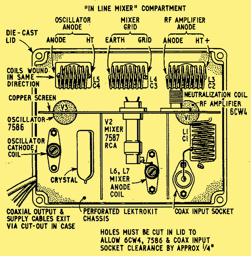
The mechanical layout of the 1969 VHF-UHF Manual's 70MHz converter.
More typical amateur applications would use Nuvistor triodes as low-noise pre-amplifiers for 70cm (432MHz), though A2521 triodes (in a B9A envelope, allowing the use of five pins for the critical grid connection), were also popular at this time. In the second half of the 1960s bipolar transistors such as the GM290 and AF139, and FETs such as the 2N3819, were also becoming more accepted in 144MHz and 432MHz converters.
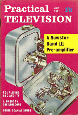
The front cover of the July 1961 issue of Practical Television featuring the Nuvistor-based band III pre-amplifier.
To return to the TV theme Practical Television published 'Nuvistor Band III Pre-amp' in its July 1961 issue The schematic of the grounded-cathode 6CW4 design is shown below.
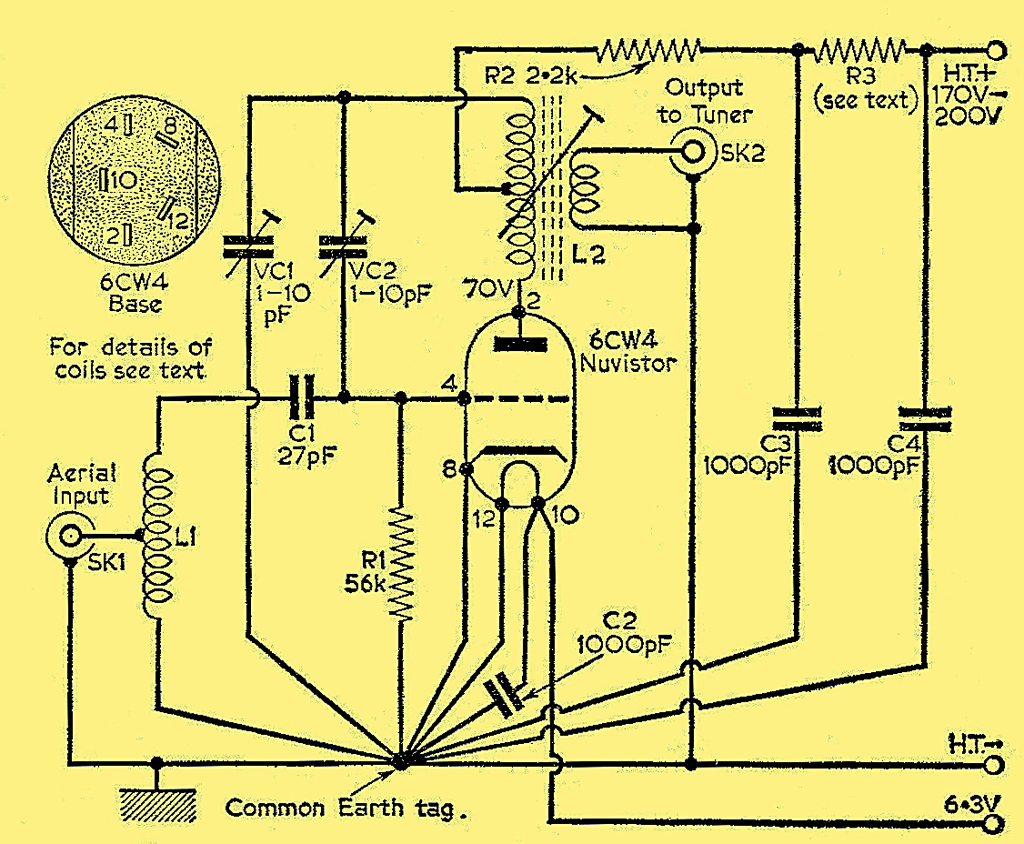
The schematic of the 6CW4 grounded-cathode pre-amplifier in the July 1961 issue of Practical Television.
TW Electronics, the well-known UK amateur radio gear manufacturer, produced a 70cm converter using an A2521 grounded grid triode in the RF stage and a 6DS4 Nuvistor in the mixer stage. Geloso, the famous Milan-based amateur radio equipment manufacturer, used the 6CW4 in many of their mid-1960s 6m, 2m and 70cm converters and transmitters. They also used Nuvistors in a range of TV sets produced in the early-1960s, and advertised the fact in 1963, as shown below.
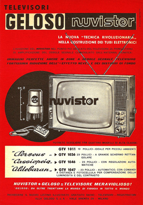
Geloso's 1963 advert indicating the use of Nuvistors in their range of TV sets.
The February 1963 issue of The Radio Constructor described two versions of an aerial pre-amplifier for a radio telescope, centred on 216MHz. One made use of the A2521 in grounded-grid mode, and the other used a Mullard 7895, described as 'the counterpart of the American 6CW4'. The purpose of the pre-amps was to give an improvement in the noise figure of the telescope of about 3dB.
Nuvistors in Military Service
The small size and rugged construction of the Nuvistor would seem to make it ideal for use in military applications. The fact that many Nuvistors also carried service codes in the UK (for example the 7587 was coded as CV8470) and Joint Army-Navy (JAN) designations in the US shows that there was much interest.
There is some evidence that Marconi tried Nuvistors in the front end of the prototype Clansman 353 radio. Although valves were used to help ruggedise the front end, it seems that in the production version the Nuvistors had been replaced by more conventional valves. Conventional wisdom indicates that valves help to 'nuclear-proof' receiver front ends: this is probably not quite true. The electromagnetic pulse (EMP) produced by a nuclear explosion is likely to disable any transistor stages of a radio and so just protecting the front end is probably not enough. It's more likely that valves were used to give the front end a wider dynamic range and tolerance to strong signals.
It is interesting to note that the Collins R390A valve-based radio, first used 'in anger' during the Korean War, was rushed back into US military service in the first Gulf War because many of the state-of-the-art solid state receivers with their transistor RF front-ends were failing due to the high static charges attributed to the desert heat, low humidity and sand storms!
In 1976 a Russian MIG-25 'Foxbat' pilot defected to Japan, and brought his plane along. Before returning the plane to its rightful owners in 30 crates the Americans took it apart and analysed its technology in great detail. What surprised them was the crudeness of the plane's structure and its avionics, and it was found that a lot of the ostensibly modern avionics in the aircraft used Russian copies of Nuvistors, for what was believed to be nuclear survivability. There was cold logic behind having nuclear-hardened hardware in manned military equipment, whether it was Russian or made in the West. Although the human crew might receive a lethal dose of radiation it would take some time for them to finally succumb and the expectation was that they would try to complete their mission in that time.
Russian Nuvistors, such as the wire-ended 6S53N-V triode and the 6P37N-V power tetrode, are still available today. These codes are best-case transliterations from the Russian Cyrillic alphabet. On the internet there are many sources of transliteration of the Russian alphabet that you might find useful: one such source is shown in [9] Transliteration of the Russian Cyrillic alphabet..
A wire-ended Russian Nuvistor type 6S53N-V, designed for high-reliability military service. You can see the insulated lead spreader at the base.
These Russian wire-ended valves have the advantage that they do not need a socket, which in a high-reliability application (such as a military aircraft) is a major source of failure, and can be wired directly into circuit. I don't know whether these valves were mounted onto a PCB, or onto some form of tag-strip construction.
Use in Sonobuoys
The RCA 8382, 8441 and 8456 triodes, and 8380 power tetrode, were designed to operate in sonobuoys. These are small floating platforms equipped with sensors, both active and passive, often dropped from surveillance aircraft, which float above potential submarine targets for some time, relaying the results from their sensors back to the circling aircraft. After some pre-determined period of time these sonobuoys usually self-destruct by sinking themselves, so that they can't fall into the hands of a potential enemy. The lower power requirements of Nuvistors (when compared to 'conventional' valves) help extend the life of the sonobuoy in the water, when of course it is operating from internal batteries.
RCA could supply these valves with heaters operating within 110% of any specified centre voltage between 6.0 and 8.5V to meet specific battery supply requirements in sonobuoys 'and other expendable equipment'.
Since they only have to survive for a short time once powered up, but they need to be very reliable for this period, components for sonobuoys were tested for 20 and 100 hour reliability, as well as short and long-term shock and sweep-frequency fatigue vibration tests. We can safely assume that these valves were not cheap!
In the US Space Program
The Ranger series of unmanned spacecraft were launched between 1961 and 1965, and were the first US attempt to obtain close-up images of the Moon's surface, in preparation for the manned landings at the end of the decade, as pledged by President Kennedy in 1961. Rangers 1-6 were all failures, and variously failed to leave Earth parking orbit, lost contact with the Earth, missed the Moon or suffered failures of their cameras. Rangers 7, 8 and 9 (redesigned from the initial craft and launched in 1964 and 1965) were successes and as they hurtled towards their destiny of crashing into the Moon sent back detailed images from their six cameras, which were extremely useful for planning the Apollo Moon-landing missions.
An interesting NASA report [10] NASA Technical Report No. 32-800: Ranger VIII and IX Part 1 Mission Description and Performance', published by JPL on January 31 1966. published in 1966 gives an interesting insight into some of the technology used on these spacecraft:
'The camera preamplifiers were reworked to incorporate either multiple-wrap leads on the Nuvistor or the new long-lead-type Nuvistors. As a result of a proof-test-model (PTM) Nuvistor failure prior to the Ranger 1711 mission, it had been determined that the Nuvistor leads which had only a single wrap before soldering were susceptible to cold joints and subsequent fracture'.
So far I've not been able to track down any US-manufactured 'long lead type Nuvistors', but as mentioned earlier the Soviets certainly made and used them.
Nuvistors were not only used by NASA in space: NASA report 'MSFN Reliability - A Summary of Theory and Results' [11] NASA report MSFN Reliability - A Summary of Theory and Results'. describes the failure of a ground-based receiver due to a defective Nuvistor in the RF tuner, which was subsequently changed.
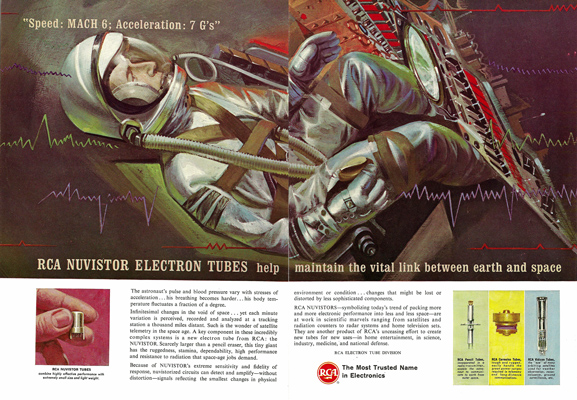
Double-page spread RCA advert from 1963 showing that Nuvistors were being used in the US manned space program. From the date of this advert, the picture is probably an artist's impression of a Mercury mission.
Above is a dramatic two-page RCA advert from 1963 showing that Nuvistors were being used in the US manned space program, specifically here in monitoring the astronaut's vital signs. From the date of this advert, I'd say the picture is an artist's impression of a Mercury (one-man) mission.
Valve Testers and Test Equipment
So as not to obsolete their equipment the manufacturers of valve testers introduced adaptors as new valve types, such as Nuvistors emerged. For example Hickok's CA-4 adaptor could be used with their Cardmatic and Roll-Chart testers to test Compactrons, Novars (B9D), 5 and 7-pin Nuvistors and Decal (B10B) valves. This adaptor plugged into the Octal socket on the tester.
Nuvistors were used extensively in test equipment produced in the 1960s and 1970s by companies such as Tektronix and Hewlett Packard. Their application was mainly in high-impedance cathode-follower vertical and trigger input circuits, and also Miller time-bases. They could also be found as the first stage in the vertical or Y amplifiers of high-end oscilloscopes. A Nuvistor was used in the plug-in wideband preamplifier module available for the Hewlett Packard 5245L 50MHz counter-timer of the 1960s.
Buying and Using Nuvistors Today
Many types of Nuvistor are still available today as 'NOS' (New Old Stock) parts. If you're interested in investing in one or two, then eBay.co.uk and eBay.com are good places to start. Make sure you have a source for the socket, otherwise you'll struggle to connect to the tiny leads! If you search for 'nuvistor project' on Google you'll get lots of hits for audio and radio projects that you might want to build.
Conclusions
Texas Instruments and Fairchild announced their development of the first integrated circuits in late 1958. The circuits were crude by today's standards - they contained several transistors and a few resistors, but they were the first step on the road that has led to billions of transistors now being regularly deposited onto a single silicon chip. The first commercial field-effect transistors (FETs) also came out in 1958. At first sight the fact that a new valve technology appeared in 1959 is surprising: it shows that at that time transistors and integrated circuits had definite limitations which allowed niche valve technology, such as the Nuvistor, to exist and even thrive for about another ten years.
Although it's true that Nuvistors were the last significant development of the small signal valve industry, it's wrong to regard them as RCA's last attempt to fend off the transistor. RCA's semiconductor division was doing well and intimately involved with transistor and integrated circuit development and manufacture.
Another valve development at about the same time was GE's Compactron multi-function valve, again designed for use in TV sets. So far I haven't managed to track down any TV chassis where Compactrons and Nuvistors co-existed.
Nuvistors filled a niche where low noise VHF and UHF amplification was needed to improve the performance of the colour TVs of the early 1960s, especially in fringe reception areas. Other applications included high-quality studio microphones, tape recorders, FM radio front ends, amateur radio equipment, and most significantly, military and space equipment. The technical excellence of Nuvistors and powerful branding by RCA helped ensure a long design-in life for the technology. TV designers in RCA moved their chassis to transistors as quickly as it was technically possible and commercially attractive, to take advantage of even greater miniaturisation, and lower costs and power. An indication of the success of the Nuvistor is that this process took more than ten years to achieve.
I've raised the possibility that RCA was the only company to actually manufacture Nuvistors in the Western world. If this is true then they must have had arrangements whereby they supplied these devices to other valve manufacturers who then offered them for sale as their own products. Readers' comments as to whether this is true would be welcome. This could explain why the prototype Clansman 353 radio used Nuvistors, but these were designed out for the production version of the radio. Maybe it had become clear by then that no UK-based (or indeed European) valve manufacturers were willing to make the investment in the production machines to make this new technology, and the UK didn't want to be dependent on RCA for supplies?
When I first started researching this article, my assumption was that TV tuners were the intended and most significant use for Nuvistors, as many Internet-based descriptions seem to indicate. Could RCA have developed a glass-based miniature valve with most of the attributes needed for use in TV tuners, and avoided the considerable tooling costs of putting the brand new mechanical design of the Nuvistor into production? The answer is probably 'yes'.
As it turned out Nuvistor technology was extremely useful, and found many applications for many more years: from microphones to missiles and audio frequencies to UHF, they triumphed where transistors still could not exist effectively. In the cold war environment of the late 1950s I think we should assume that RCA's designers already had military and space uses for these valves in mind, even as they were testing the first prototypes and perfecting the novel production process. The technical excellence of Nuvistors and powerful branding by RCA helped ensure a long design-in life for the technology.
For the fans of conspiracy theories among you, I'll just say how convenient for the US space program and military industries that a miniature, low power, static-proof, nuclear-hardened and rugged technology, with a plausible cover story, should happen to be developed at a time when it was needed the most.
References
- 'Acorn Antiques - High Frequency Valves Ready for War' by Stef Niewiadomski. Radio Bygones Issue No.128 (Christmas 2010) and No.129 (February/March 2011).
- 'RCA Nuvistor Tubes for Sonobuoy and other Expendable Equipment'. Published by RCA in September 1963.
- '70 Years of Radio Tubes and Valves' by John W Stokes. Published in 1982 by The Vestal Press Ltd, New York.
- The schematic of the Ampex MR-70 tape recorder.
- 'New High-Grade Condenser Microphones parts 1-4' by F W O Baugh. Published in Wireless World February-May 1953.
- A description of the restoration of a 1962 RCA CTC-11 colour TV.
- RCA's CTC-7 chassis RF arrangement was described in detail in the RCA Review for September 1953.
- The schematic of the 100% valve Kenwood KW-1100U AM/FM tuner.
- Transliteration of the Russian Cyrillic alphabet.
- NASA Technical Report No. 32-800: Ranger VIII and IX Part 1 Mission Description and Performance', published by JPL on January 31 1966.
- NASA report MSFN Reliability - A Summary of Theory and Results'.
General References
RCA published a series of brief manuals on Nuvistors. Among them are:
- 'RCA Nuvistors - Industrial and Military'. Published in 1962.
- 'RCA Nuvistors - 6DS4, 2DS4 High-mu Triodes with Semi-remote Cut-off Characteristic for TV and FM Tuner Designs'. Published in July 1962.
- 'RCA Nuvistors - 2CW4, 6CW4 High-mu Triodes for TV and FM Tuner Designs'. Published in July 1962.
- 'RCA Nuvistor Tubes for Sonobuoy and other Expendable Equipment'. Published in September 1963.
There is plenty of Nuvistor data on the Internet. Some useful links are at:
The following links give interesting sources of data on the 'New Vista' and previous generations of RCA TVs: 1 2 & 3.
A useful overview of Nuvistor technology and circuits for use at VHF can be found in 'Practical Nuvistor Circuits' by K Royal, published in the December 1962 issue of Practical Television.
The article mentions the RCA 6CW4 and Mullard 7586, 7587 and 7895. In this issue Bentley Acoustic Corporation Ltd are selling the 6CW4 for 24/-: the magazine has a cover price of 2/-.
The history of TW Electronics was published in Practical Wireless for September 2002, and a scan of this article can be found here.
Sources of Valve Data
There are many sources of data for valves, for example:
Radio Valve and Transistor Data (published by Iliffe). various editions.
ARRL Radio Amateurs Handbook various 'valve period' editions.
Here at The National Valve Museum
I think it's easier to get valve data today than ever, because of the heroic actions of people who have entered manufacturers' data from scratch, scanned data sheets into pdf and gif format and made them available on the Internet. Some sources of data that I use are:
A useful website on valves, with a section dedicated to Nuvistors can be found here.
Additional Information
In 2021 Dr David Land reported that Nuvistors were used in the specialised CCTV cameras made by Pye TVT in the 1960s for nuclear reactor core inspection.
|