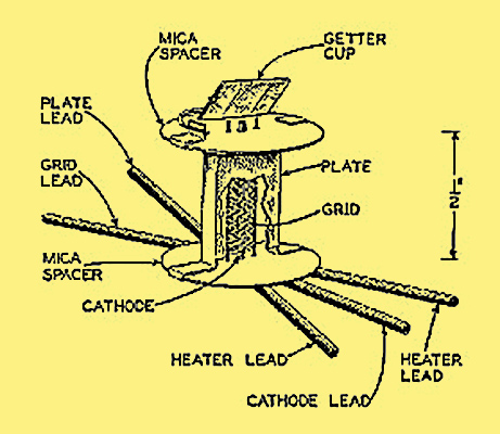
Above: a cut-away diagram of the 955 triode showing what the internal construction looks like.
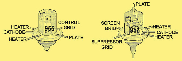
The 955 and 956 pin connections. The 956 has its control grid connection, which is the lead coming out of the bottom of the envelope, unmarked on this diagram.
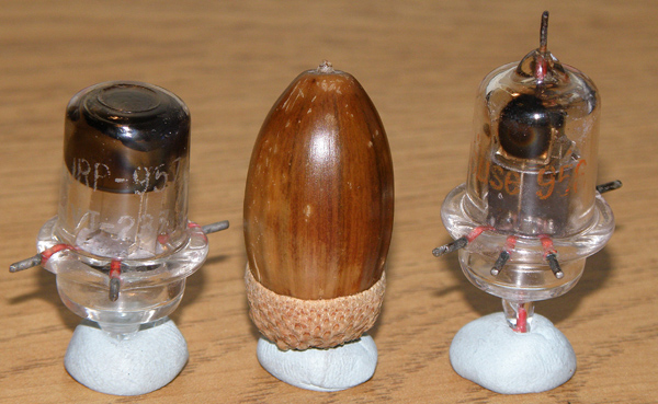
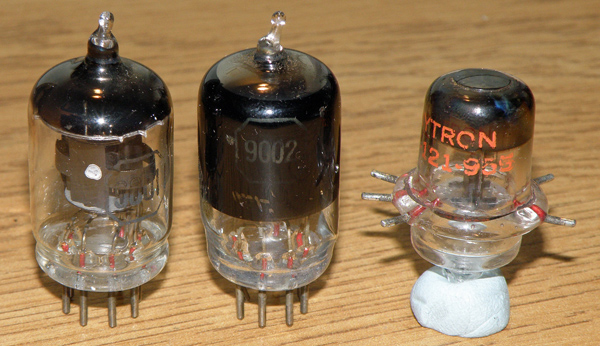
Below: an acorn valve family line-up. Left to right, they are the 954, 955, 956 and 957, some in various military guises. As you can see from the presence or absence of the top lead, we have pentode-triode-pentode-triode in the line-up.
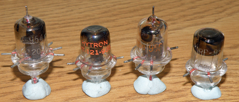
An acorn valve family line up. Left to right, they are the 954, 955, 956 and 957, some in various military guises.
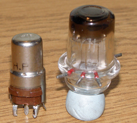
The shape of these valves necessitated the introduction of a new socket format. The image below shows a Hytron VT-121-955 triode sitting on a ceramic socket. The five pins need to be pushed into the clips in the socket. The second image shows a couple of styles of clip-on connectors for making contact to the top and bottom pins of the acorn pentodes.
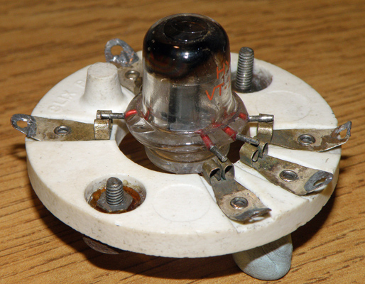
A Hytron VT-121-955 triode sits on a ceramic socket. I haven't dared to push the five pins into the clips in the socket. See Acorn Valve Base for a solution.
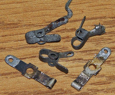
A couple of styles of clip-on connectors for making contact to the top and bottom pins of the acorn pentodes.
While these valves were intended for use at VHF/UHF frequencies their small size had an appeal of its own. Though I've not managed to track one down yet there was at least one constructional article on building a broadcast remote console with the 955, and the valves were also used in radio control receivers and transmitters.
Acorn Numbering
A note on the 954, 955, etc. numbering of these valves: at the time these valves appeared RCA were following what would soon become the standardised US RMA valve coding system, which gives us the 6V6, 12A6, etc. However valves could also be numbered with an all numeric code. These all numeric codes were normally reserved for 'special purpose' valves, which shows the experimental nature of these acorn valves. Later use of the standard codes of '6F4' (acorn oscillator triode, for use up to 1200M, or '6L4' (acorn oscillator triode, capable of running with 500V on its anode) for some acorn valves indicates that the technology had then become more 'main stream' and no longer merited a 'special' code number.
I've tried to show in Table 1 all the acorn valves I could find, from various sources, along with some of their characteristics and equivalents.
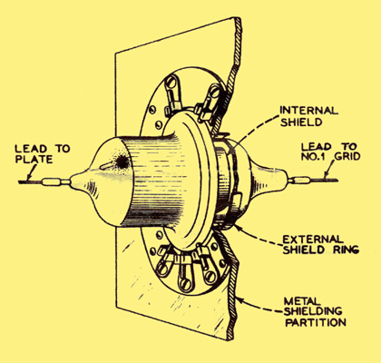
Diagram from RCA's 956 data-sheet showing how the plate (anode) circuit is isolated from the No. 1 (control) grid by a combination of internal and external shielding.
RCA thoughtfully packed a data sheet [1] Original RCA data sheet for the 956 in with each valve, as was common practice with many manufacturers. Above is a scan of part of the 956 data sheet showing chassis mounting details for maximum isolation between the grid input and the anode (plate) output circuits.
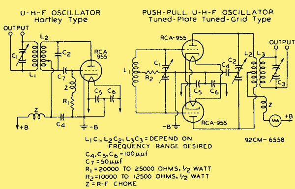
A couple of UHF oscillator circuits using the 955, provided by RCA on its data sheet.
Several US manufacturers made acorn types, particularly 955s, during WW II. As a result, most tubes found today are ex-military, and carry Joint Army-Navy (JAN) designations in either a long form or an abbreviated version ahead of the tube type number. The known makers are: GE (JAN-CG or JG); Hytron (JAN-CHY or JHY); Raytheon (JAN-CRP or JRP); RCA (JAN-CRC or JRC); Sonotone (JAN-COZ or JOZ); Tung-Sol (JAN-CTL or JTL); Westinghouse (JAN-CWL or JWL).
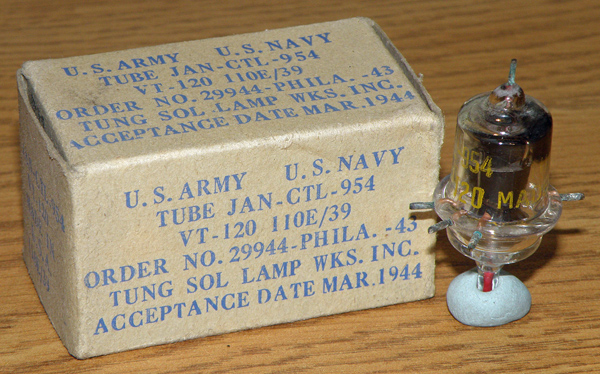
A Tung Sol JAN-CTL-954 next to its box, which tells a story in itself. The code 'CTL' indicates Tung-Sol manufacture: other manufacturers had their own codes, as described in the text.
Acorn valves are definitely in the category of 'miniature' valves. If you want to see some even smaller 'sub-miniature' ones, take a look at the Tung-Sol 6418 pentode (intended for 'portable and wearable equipment', that is hearing aids, and about 1 inch long by ¼ inch diameter) or, staying more on subject, the 5908, a UHF mixer pentode at just over 1 inch long and 0.4 inch diameter. An interesting article on how this type of miniscule valve was manufactured can be found in [2] 'Notable Advances in Valve Manufacturing Techniques 1952' by K J Lloyd. The BVWS Bulletin, Volume 30 No 3, Autumn 2005.
Acorn Diodes
Two acorn diodes were added to the line-up for WWII military equipment: the 9004 and 9005. The 9004 was quoted as having a 'resonant frequency of 850MHz' on the 1942 data sheet, and found use in radar altimeters. To aid in matching pairs of 9004s, each valve carried a 'zone' number, between 1 and 6, marked at the top of the glass envelope to indicate its relative emission, as verified under test conditions. The 9005 was quoted as having a 'resonant frequency of 1500MHz', had the strange heater voltage of 3.6V, AC or DC. I presume some special application was in mind when this valve was designed.
Although promoted as UHF detectors (that is rectifiers of low level signals) 9004 and 9005 acorn UHF diodes/rectifiers were rated at 117V PIV, so I suppose in theory at least one of these valves could have been used as the AC mains rectifier stage in US-mains powered equipment. The non-acorn 9006 (see Table 2), again though publicised mainly as a UHF diode had a maximum PIV rating of 750V (!) at 5mA.
Mullard Acorns
Mullard released its own acorn designs: the AP4 pentode 'for operation as detector or HF amplifier at ultra high frequencies', was launched in 1937. This valve was priced at 60/- (equivalent to somewhere between £144 and £560 in today's money, depending how you measure it), so definitely not a cheap valve by any means. This valve acquired a couple of military code numbers, CV1175 and CV1176, so it would seem that it found itself used in military equipment. Mullard also produced a triode acorn in the same envelope format, namely the AT4, priced slightly cheaper at 50/-, and this valve acquired the military number CV1171. Both the AT4 and the AP4 had 4V, 250mA heaters.
For some reason Mullard chose to set the angle between the grid and anode (on the AT4 triode) and between the suppressor and screen grids (on the AP4 pentode) at 90°, whereas the RCA versions had this angle set at 60°, which meant that two types of sockets had to be produced to accommodate the two valve types.
Amateur use of these Mullard acorns seems to have been relatively rare (maybe because of the high cost, before the war at least) and I was unable to find many designs using these valves. The amateur market doesn't seem to have become flooded with war surplus AP4s and AT4s in the same way that happened with the 95x series of acorns. In fact the only mention of the Mullard valves in a constructional article I could find was in volume 4 of the Eddystone Short Wave Magazine which describes an 'Ultra Short Wave Receiver for the 5 metre amateur band (68MHz to 51.4MHz)'. The design uses a Mullard AP4 acorn for the 'HF stage', that is the RF amplifier [4] 'Ultra Short Wave Receiver for the 5 metre amateur band (68MHz to 51.4MHz)'. Volume 4 of the Eddystone Short Wave Magazine, published in 1938..
A Weakness of the Acorn Valve?
Because the acorn valve does not have a base as such, the pins pass directly through the glass and can be subjected to side force stresses as they are inserted and removed from their socket. Other glass-seal valves such as the B7G or B9A also seal the pin directly to a glass base, but the pins do not experience a side force, which has the potential to fracture the glass. Of course in the case of the acorn, there are five pins that are being inserted or removed at one time, so it can't have been easy to get it right.
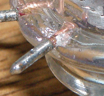
A 'soft' VT-121 triode.
To make the point, if you look at picture, a photograph of a 'soft' VT-121 triode (equivalent to the 955) hopefully you can see where the glass around one of the heater pins has cracked, destroying the vacuum of the valve and rendering it useless.
Since these valves saw considerable military service, once they were safe and snug in their sockets (having being inserted there in the factory), they were clearly very reliable. Presumably 'in field' removal and replacement of acorn valves must have been restricted to a well documented and controlled process. Maybe some unofficial removal/insertion devices were knocked up (maybe a length of pipe of the right diameter?), but I can find no mention of this anywhere in the literature.
The Philips 'Miniwatt'
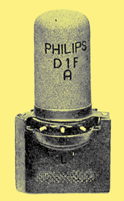
The Philips D1F 'Miniwatt' pentode. Note that it has no pins sticking through the top or bottom of the glass, all the pins being accommodated around the circumference of the envelope. Also the glass is covered in a metallisation layer.
Philips produced a range of miniature valves, called the 'Miniwatt' series, advertised as 'The valve for portable transceivers'. These used the basic principles of the RCA acorns, though the envelopes and bases are slightly different, so I'm not sure I should strictly include them under the category 'acorns'. The picture shows the shape of these valves, and note that although this valve (a D1F) is a pentode it has no pins sticking through the top or bottom of the glass, making the valve even more compact than the RCA design. Also the glass is covered in a metallisation layer. As for the RCA range, there were 6.3V and 1.4V heater versions for fixed and portable operation.
These valves were specified as having low distortion when used as AF amplifiers, so they were definitely intended for use in all stages of a compact transceiver.
The data sheet for the D1F/D11F Miniwatt valves describes the use of a handgrip, which I presume solved the problem of insertion and removal of the valves to and from their sockets. In fact the data sheet indicates that 'valves can easily be replaced without opening the set'.
Other Manufacturers
Marconi seems to have produced a couple of acorn valves, namely the ZA1 and ZA2. Not much information on these two valves seems to have survived, but I'm pretty sure the ZA2 was a triode, equivalent to the 954, so presumably the ZA1 was a pentode. (also M-OV produced the HA1 & HA2-ed)
There was a DSxxx series of acorn valves, manufactured by Lorenz in Germany which I believe was used in German military equipment during the war.
Hallicrafters and National Adopt the Acorn
Acorn tubes appeared in the front ends of several well known US-produced prewar and wartime VHF receivers, for example, the Hallicrafters S-27, S-36, and S-37, and the National 1-10.
National produced the 1-10 (so called because it covered the range from 1m - 10m, that is, about 300MHz down to 30MHz) and the 1-10A, specifically covering the VHF range from 28 to 280 MHz. The receiver design was 'experimental' in nature, being pretty basic, not even having an output transformer (though maybe this isn't too unusual in the days of high impedance 'phones that would have been connected between the anode of the audio output valve and the HT supply).
The two models differ primarily in cosmetics: for example the dial is on opposite sides of the front panel for the two models, which confused me at first as I thought some photos of the receiver had been published as mirror images. Both receivers used a 954 in the RF stage and a 955 self-quenching super-regenerative detector, with a 6C5 and a 6F6 in the audio stages. An external power supply was needed. The receivers used the famous HRO dial (more exactly known as the 'Micrometer' dial) and two plug-in coils for each range, accessed through the hinged lid.
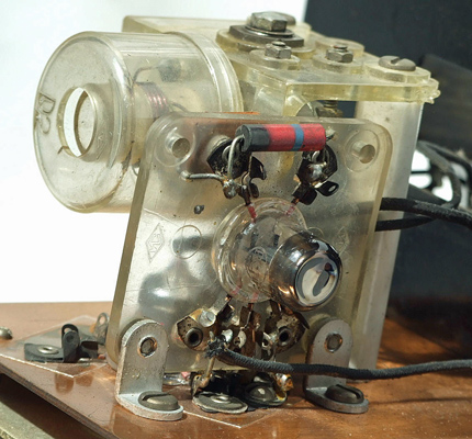
A view (courtesy of Ben Nock G4BXD) of the National 1-10's UHF RF compartment, showing the 955 super-regenerative detector valve. The 954 RF amplifier stage can just be seen through the Perspex bracket holding the 955's socket. The cylinder marked 'D2' is one of the pair of plug-in coils for each of six ranges.
See above for a view of the 1-10's front end compartment showing the 955 detector stage. Below is an 1947 advert for the 1-10A, when it cost $67.50, without power supply or loudspeaker unit, which presumably contained the output transformer.
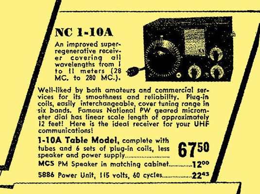
Part of a June 1947 advert (from QST magazine) for the National 1-10A receiver.
Acorns in Military Service
As you can see from Table 1 the 954-958 range were allocated many UK military CV (common valve) and US military VT (Vacuum Tube) codes, implying that they had high reliability specifications imposed for use in military equipment. Of course these valves arrived on the scene just as the world was about to go to war and found many applications as the impetus of technical warfare drove electronics towards ever higher frequencies. (Acorns were later blacklisted See here-ed)
The British Army Wireless Set 19 entered service in 1941 and its 'B' set (intended for short range vehicle-vehicle communications) covered 230-240MHz, making use of the E1148/CV6 VHF triode (having an octal base) for the RF amplifier and oscillator. This shows the limits of what could be achieved at the time with 'old' technology.
Several British military receivers and transmitters made use of acorn valves. For example the Marconi-produced DFP5 VHF Direction Finder receiver, (produced for the British Army, but also used by the RAF) used a 954 and a 955, and gave a frequency coverage of 30-300MHz in AM and CW modes. The set was powered from 6V DC.
Because of their small size, acorn valves found their way into several clandestine radio designs. For example the MI9 clandestine/survival cigarette case midget transmitter and receiver used 2-off 955s and 2-off 954s; and the clandestine/spy receiver type 53/1 used 3-off 9001s. In the same category, the transmitter/receiver Mk.18 set used a 9001 and 2-off 9002. This set was intended for short range VHF communication with planes or ships. My thanks go to Louis Meulstee (author of the Wireless for the Warrior series of books) for providing information on some British military sets using acorn valves.
Knowledge on the use of acorn valves, either of UK or US origin, in British military sets is definitely patchy, and more work needs to be done to research this. More information seems to be available on the internet on the use of acorn valves in US military equipment. If you take a look at reference [6] Acorntube., you'll see a long list.
Competition Arrives
A 9001 and a 9002 alongside a 955 acorn. The B7G valves are not much bigger than the 955, especially when you take into account the wide socket the acorn would have to plug into.
Well before the transistor era arrived, competition appeared for the acorn valve. As early as 1943 RCA introduced the 9001, 9002 and 9003, which were designed to be electrically similar to the 954, 955 and 956 respectively, and packaged in the new all-glass B7G envelope, designated as a 'midget' type. I suspect by this time the drawbacks of the acorn valves' mechanical construction had become evident, and the B7G design of the 900x series was capable of equivalent performance in the more conventional (that is, the pins came out of the end) glass envelope, which of course was much easier to insert and remove from a socket. You can see from the image above that the 9001 and 9002 are not that much bigger than the 955, especially when you take into account the wide socket the acorn would have to plug into.
Other VHF/UHF valves, such as the 6Q4, A2512 and 6AM4 (CV5073) later appeared in the 9-pin all-glass B9A envelope. You may be used to seeing other B9A valves (for example the EL84) in quite long envelopes, but these UHF valves were typically only 1= inch long, which was all that was needed to dissipate the relatively small amount of heat generated in these small signal valves. These were all triodes and the rationale behind using a 9-pin envelope was that this allowed five pins (usually pins 1, 3, 4, 6, and 9, evenly spaced around the base, and often gold plated), to be used to bring out the grid connection, keeping a very short and therefore very low inductance connection to ground for this critical path in grounded-grid applications. Brimar rated its 6AM4 'for amplifier or mixer use in the frequency range 470 to 890MHz'.
I've made a list of a few competitor valves to the acorn in Table 2, but this is by no means comprehensive.
Nuvistors
RCA announced the Nuvistor triode and tetrode valves in 1959, as a last fling of valve technology, for use in TV VHF and UHF tuners, from where they were finally displaced by transistors in the early 1970s. This valve is shaped like a thimble, but somewhat smaller at about 20mm high and 11mm in diameter. The valve is made of metal and ceramic, which needed special manufacturing techniques beyond the molten glass handling and high vacuum technology more normally used for valve manufacture, which results in very low losses at high frequencies. You may have heard of the 6CW4 which was used in many amateur UHF amplifier and converter designs. Nuvistors are capable of excellent VHF and UHF performance, with very low noise figures.
An acorn valve (a 957) alongside an RCA 6CW4 Nuvistor (plugged into its socket) so you can compare them side-by-side. The diminutive size of the Nuvistor can clearly be seen, the length of its metal body being about = inch.
Above is an acorn valve (a 957) alongside an RCA 6CW4 Nuvistor (plugged into its base) so you can compare them side-by-side. As you can see the Nuvistor is considerably smaller than the acorn, and its very compact base adds very little to the space needed.
A fuller history of the Nuvistor can be found by following the link.
Acorns in Amateur Service
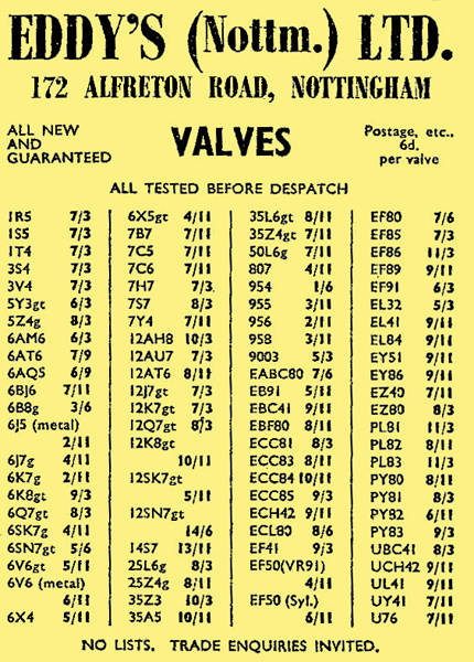
An 'Eddy's (Nottm) Ltd' advert from the mid-1950s showing the costs of some acorn valves.
Acorn valves found their way into many amateur designs in the 1940s, 50s and 60s, as large numbers of what were by then obsolete devices were released by the MOD onto the surplus market after the end of the war. The image above shows an 'Eddy's (Nottm) Ltd' advert from the mid-1950s showing the costs of some acorn valves. Assuming it's not a printing error, at 1/6 the 954 looks like a bargain! Note also how cheap the beefy 807 is: no wonder it found its way into many transmitter designs of the period.
At the end of this article I've included a long list of acorn designs that have appeared in amateur literature over the years, and I'm sure there were many more published that I haven't spotted.
Eventually in amateur designs the low noise E88CC double-triode became popular as a cascode RF amplifier in 70cm (432-434MHz) converters and receivers. This valve used a B9A base, and as long as a low-loss socket was used, there was no disadvantage over the specialised (and awkward to mount) acorn format. The E88CC was about twice the cost of its better-known double triode cousins, the ECC81/82/83. Another popular valve was the A2521 triode, which was used in several amateur designs and features often in the RSGB VHF/UHF handbooks.
Eventually of course, transistors displaced all (well most) valves circuits and even early-ish germanium transistors (such as the AF239 and the ADT140) were capable of good performance at VHF. I've included a few references to these applications at the end of the references section.
As an indication that interest in the quirky acorn valve is not dead, as recently as summer 2007 a couple of 'nostalgic' acorn transmitters, generating a few hundred milliWatts of output power, appeared in SPRAT (see references [8] 'Acorn Valve Transmitter on 40m' by Walt Bullerwell, KF4YJQ. SPRAT Summer 2007. Uses a 955 to give 200mW output with 135V anode voltage. & [9] 'An Acorn Transmitter' by Johnny Apell, SM7UCZ. SPRAT Summer 2007. Uses a 955 to give 400-500mW at 150V anode voltage.).
US Amateur Practise
I don't have a great collection of 1950s and 1960s US radio magazines, but as far as I can see, US amateur practice pretty much followed what was going on in the UK (or maybe the other way round?). There was a mixture of acorn-type projects for portable VHF applications: see for example reference 10, making use of the 957 triode in a super-regenerative detector and 959 as a pentode RF amplifier, both having 1.25V heaters; and grounded-grid B7G- and B9A-based triodes for UHF converter use. For example, reference 11 describes a 70cm converter using a pair of 6AN4s cascaded RF amplifiers in grounded-grid mode, feeding a passive 1N82 crystal diode mixer stage converting down to 14-18MHz.
Conclusions
As with any technology, innovations in valve design were often very significant at the time of introduction but faded into disuse after just a few years. Acorn valves are a stark reminder of this and having greatly eased the problem of building equipment for VHF and UHF frequencies during the late 1930s and early 1940s, especially in vital military equipment, they were soon superseded, in most professional and military applications at least, by newer valve designs and construction techniques.
Most manufacturers of acorn valves, and the valves themselves, are well documented, but Marconi's and Lorenz's offerings are less well know and are worthy of more research.
After the war amateurs continued to make use of the vast, easy and cheap supply of acorn valves, having been produced in their millions during the war. Even today the occasional project pops up using these quirky and attractive-looking valves. Acorn valves and their special sockets appear continually on eBay, if you fancy giving one a try.
References
- Original RCA data sheet for the 956.
- 'Notable Advances in Valve Manufacturing Techniques 1952' by K J Lloyd. The BVWS Bulletin, Volume 30 No 3, Autumn 2005.
- Mullard AP4 data-sheet.
- 'Ultra Short Wave Receiver for the 5 metre amateur band (68MHz to 51.4MHz)'. Volume 4 of the Eddystone Short Wave Magazine, published in 1938.
- Data sheet for the Philips D1F/D11F 'Miniwatt' valves.
- Acorntube.
- Nuvistors in Radio History
- 'Acorn Valve Transmitter on 40m' by Walt Bullerwell, KF4YJQ. SPRAT Summer 2007. Uses a 955 to give 200mW output with 135V anode voltage.
- 'An Acorn Transmitter' by Johnny Apell, SM7UCZ. SPRAT Summer 2007. Uses a 955 to give 400-500mW at 150V anode voltage.
- 'A Club-Project 2-Meter Portable' by Carl H Ericson, W2PPL. QST April 1956.
- 'A Crystal-Controlled 432MHz. Converter' by Ernest J Bernard, W5NSJ. QST March 1956.
Other Useful References
As well as the numbered references above, referred to specifically in the text, I have found many other useful references to acorn-based projects, and other VHF/UHF techniques in competition with the acorn.
- 'Special Tubes for Ultra-Short Waves'. Short Wave Radio Craft March 1935. Describes some German valves with their anode, grid and cathode terminated in 'binding posts' on the top of the glass bulb. Only the heater pins were connected via the normal base.
- Amateur Radio Microwave Technique, a booklet published by the RSGB in October 1947.
- 'Four-Twenty is Fun!' by E P Tilton, W1HDQ. QST November 1947. A 420MHz receiver using a 955 triode detector.
- 'Let's Start Right on 1¼!' by Calvin F Hadlock, W1CTW. QST December 1947. A 235MHz receiver using a 954 pentode RF amplifier and a 9002 in the HF oscillator.
- 'A Modern Walkie-Talkie' by Charles P Eller, W2SVI. CQ Magazine, October 1948. A 2m transmitter/receiver using 2-off 958A.
- 'Multi Purpose 7-way Test Meter from surplus gear' by W Oliver G3XT. Radio Constructor January 1949. 'This versatile instrument was made from an ex-Service surplus unit, the US Army Signals Corp Control Box BC-1150-B, which cost 10/- at a local garage'. Uses 6.3V (from mains transformer) acorn diode, or triode strapped as a diode.
- 'Combination VHF Monitor' CQ Magazine, April 1949. Uses a 957 and a 1N34 germanium diode.
- 'Surplus Acorn Valves' by E G Bulley. Practical Wireless April 1952. Describes several acorn types and circuits.
- 'Building the RCS Battery Receiver (part 3)' by James Sinclair. Radio Constructor September 1954. Three acorn valves are used.
- 'A Pre-selector for the RCS Battery Receiver' by J Sinclair. Radio Constructor May 1955. Uses a 954 pentode.
- 'Making a 2-Metre Walkie-Talkie' by R Moores. Practical Wireless September 1955. Uses a 957 as a super-regenerative detector.
- 'Using VHF Acorns' by F G Rayer. Radio Constructor July 1956. Uses a 955 triode and a 954 pentode.
- 'An Acorn AC All Wave Signal Generator' by F G Rayer. Practical Wireless February 1957. Uses a 954 pentode.
- 'A Personal Portable Receiver' by James Sinclair. Radio Constructor December 1959. Uses a 954 pentode connected as a triode, that is the anode and suppressor grid are not used, and the screen grid is used as the anode. Also describes a conversion to two valves (another 954) for more audio output. The RCS Products (Radio) Ltd kit sold for 35/-.
- 'Circuits for Acorn Valves' by L V Nixon. Practical Wireless January 1961. Uses a 954 and a 955.
- 'Beginner's Short Wave Two' by F G Rayer. Practical Wireless November 1963. Operates up to 100MHz, using a 954 pentode.
- 'Short Wave One' by C J Mitchell. Practical Wireless March 1964. Uses a 955 triode (or a 954 strapped as a triode).
- 'A Two Stage VHF Feeder Unit' by A Sydenham. Practical Wireless June 1964. Uses a 954 pentode.
- 'Getting Going on UHF' by J P Billingham G8AAC. Practical Wireless November 1966. Lots of valves and Silicon and Germanium transistors mentioned, but no acorn valves.
- 'The Explorer AM/VHF Receiver' by W E Bargett. Practical Wireless January 1967. Uses ADT140 PNP Germanium transistors as tuned RF amplifier and super-regenerative detector. Covers 65-170MHz.
- 'Receiver for 144MHz' by F G Rayer G3OGR. Practical Wireless February 1967. Uses a 954 pentode RF amplifier to isolate the aerial from the oscillating super-regenerative 6C4 detector.
- '70cm Converter' by J P Billingham G8AAC. Practical Wireless May 1967. Uses an E88CC cascade RF amplifier.
- '70cm Preamp' by J L Oliver G8ANJ. Practical Wireless July 1967. Uses an AF239 Germanium PNP transistor off a -9 to -12V supply.
- 'Simple Two-Metre Converter' by J L Oliver G8ANJ. Practical Wireless November 1967. Uses an E88CC cascade RF amplifier.
- 'Wide Range Grid Dip Oscillator' by R G Lamb. Practical Wireless February 1969. Uses a 955 triode and operates over the range 170kHz - 150MHz.
- 'CQ2 VHF Receiver' by M J Gordon. Practical Wireless September 1969. Uses the MPF102 JFET as super-regenerative detector.