|
Amplifiers for quality reproduction seem to have reached a point where the design follows a generally accepted pattern of pentode voltage-amplifying stage, phase inverter and push-pull output stage, the power output being in the region of 10 to 15 Watts of audio with low distortion. Negative feedback in some form or other is usually incorporated to linearize the frequency response, reduce distortion, and improve the damping factor.
The design presented here does not depart essentially from these basic requirements, although it has certain features that result in ample output for normal uses, good reproduction, and simple circuitry. It is not unduly large or heavy, nor is it expensive or difficult to build. Tone controls for treble and bass are included, and the output stage is operated in Class AB1 under distributed load (or 'ultra-linear') conditions. A less usual feature for an amplifier of this type is the use of a small amount of positive feedback which improves the damping factor of the speaker.
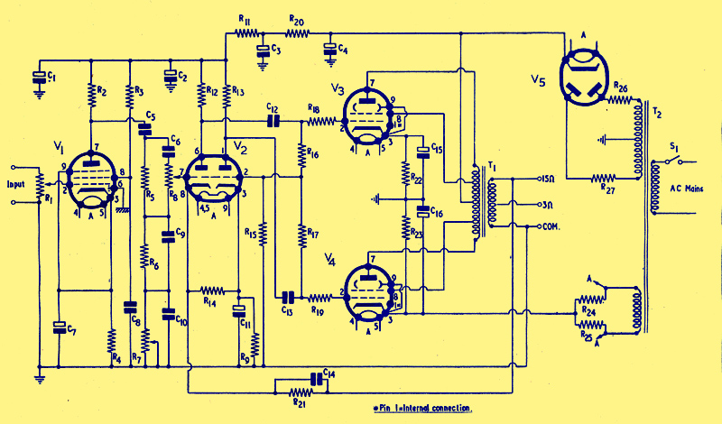
Fig. 1. The circuit of the Virtuoso amplifier
The circuit is shown in Fig. 1. The input stage is the usual voltage-amplifying pentode, using a Brimar 6BR7, which was chosen for its low hum factor and high stage gain. Input is controlled by the 500kΩ potentiometer R1, and it will be seen that the circuitry around this valve follows normal practice. Correction networks for various forms of input are not included since these will depend upon the equipment used to drive the amplifier.
The tone control network for bass and treble is connected between the anode of V1 and the grid of the first section of the phase inverter stage V2. R7 is the bass control and R8 the treble control. Values of components in the network are such that about 15.5dB boost is obtained with the controls at their maximum positions, on the assumption that the 3dB points for bass and treble are 200 Hz and 2 kHz respectively. If desired, values of the components can be altered in accordance with the formulas given below to give other degrees of boost and for different frequencies for the 3dB points. The value of R5 is approximately the input impedance of the network over most of the range. Normally it should not be less than 100kΩ. In practice, it will be found that values of 100kΩ or 200kΩ for R5 are the most practicable, since the values of R7 and R8 are entirely dependent upon it. At the same time, one is restricted to standard values of potentiometers, and values higher than 2MΩ are seldom obtainable as stock items.
By applying the formulas in the order given, the values for the other components can be worked out in logical sequence. It should be noted, however, that the quotient obtained by dividing the desired boost (dB) by 20 is to be treated in the calculation as if it is a logarithm and the actual antilog found from log tables in the usual way. If, for example, dB/20 is 0.9675 this is regarded as a logarithm whose characteristic is zero and the mantissa .9675.
In the formulas below, f1 is the low frequency (bass) 3dB point, f2 the high frequency (treble) 3dB point, both of which values should be inserted in terms of Hz. Values of R are in Ohms, and C is in μF and pF where stated. Wherever possible, the working should be shortened by using indices to powers of 10.
R5 = not less than 100kΩ
R7 = R8 = 10R5
R6 = R5 / ((antilog(dB/20))-1)
C10 = (1.6 x 10⁵) / (f1 x R5)μF
C6 = f1 / f2 x 105C10pF
C9 = R8 x C6 / 10R6
An example will assist in showing the use of the formulas. Assume the requirements to be 22dB boost; with the bass and treble 3dB points at 320 Hz and 3.2 kHz respectively. R5 is to be 100kΩ. Applying each formula in turn:
R7 = R8 = 10R5
= 1.0MΩ
R6 = R5 / ((antilog(dB/20))-1)
= 105 / ((antilog(22/20))-1)
= 105 / ((antilog(1.1000)-1)
= 105 / (12.59 - 1)
= 104 / 1.159
= 8.63 x 103
= 8.63kΩ
This is not a standard value, the nearest values in 5% tolerance being 8.2kΩ and 9.1kΩ. The required value could be obtained with 10kΩ in parallel with 62kΩ, which gives 8.61kΩ
C10 = (1.6 x 10⁵) / (f1 x R5)μF
= (1.6 x 10⁵) / (3.2 x 102 x 105)
= (5 x 10⁻¹) / 102)
= (5 x 10⁻³)
= 0.005μF
C6 = f1 / f2 x 105C10pF
= (3.2 x 102 x 105 x 5 x 10-3) / 3.2 x 103
= 5 x 10
= 50pF
C9 = R8 x C6 / 10R6
= 106 x 5 x 10 / 8.63 x 104
=5 x 10³ / 8.63
= 5.8 x 102
=580pF
The output from the tone control network is taken to the Brimar 12AX7, connected as a floating paraphase self-balancing phase inverter. This particular circuitry was chosen for its simplicity and stability, bearing in mind the ease of applying positive feedback to it. The necessary feedback is obtained through the 200Ω resistor R14 which is common to both cathodes. The tolerances of R15, R16 and R17 should be not less than 5%, and for preference they should be 2%. In any case, R15 and R16 need to be matched to within 2% of each other. Similarly, although the anode loads R12 and R13 need not be close- tolerance values, it is advantageous for them to be closely matched.
The anti-phase output from V2 is fed to the Brimar 6BW6 output valves via capacitors C12 and C13. Grid stoppers R18 and R19 prevent any tendency to parasitic oscillation in the power output stage. It is important that the 6BW6s are operated at a maximum HT voltage of 285 Volts. If this value is exceeded there is danger of damaging the valves due to excessive screen current. Separate cathode bias resistors and bypass capacitors are used in preference to a common cathode resistor in order that slight adjustment can be made to either R22 or R23 to match out the standing anode current through the output transformer primary. These resistors have nominal values of 260Ω, obtained by connecting 330Ω in parallel with 1.2kΩ for each. Adjustment can then be made by using a higher or lower value in place of the 1.2kΩ branch so that a voltmeter connected across the output valve anodes reads zero at balance.
Negative feedback is taken from the output transformer secondary to the cathode of the first section of V2, via a phase correction network consisting of R21 and C14. The values of these two components are not critical, but if other values than those specified are used, they should multiply to 1.0. It will be seen from Fig. 1 that R21 in Ohms, multiplied by C14 in microfarads, is 1,000 x 0.001 = 1.0. This simple network has the effect of increasing the high frequency at which the amplifier loop gain is likely to run into positive feedback due to phase change.
When this amplifier was designed and built some three years ago the distributed load (or so-called ultra-linear) configuration for output stages was much less popular than it is now, and suitable output transformers were not so readily available commercially to the extent they are today (see addendum). It was, therefore, necessary to design and make a suitable transformer, details of which are given later for those who would like to copy it. In those days, too, there was little information in the popular literature concerning the optimum tapping point in the primary sections to which the screens are connected, although some sources had expressed the view that not all valve types required tapping in at the same point. In the prototype transformer, several primary taps were brought out for experimenting, and the feature has been retained so that feed points for the screens can still be altered if needs be.
The overall effect of altering the screen tapping point affects the output stage characteristics in several ways at once, and it is not at all easy to show mathematically just what happens. Graphs of different parameters, obtained by measurements, reveal that for a particular type of valve there is an optimum tapping point at which the valve is working partially as a triode and partially as a pentode. The valve will then assume the high gain of a pentode and the comparatively low distortion of a triode, and will be working at optimum points on parameters for inter-modulation distortion, output damping factor, and power output.
It will, perhaps, be seen fairly readily that if the screens are connected directly to the primary centre-tap, or HT, the valves will be pentode connected, and will operate as such. At this point none of the primary load is distributed to the screens, and there is no feedback to them. If the screens are taken to the outers of the primary, the valves will obviously be triode connected, and will tend to function as triodes. In this condition the primary load impedance is distributed to the screens equally, and there is maximum feedback. At various points between the centre tap and the outers of the primary, different values of primary impedance will be distributed to the screens as the tapping points are made at various places. If the tapping points are moved from the outer ends towards the centre tap of the primary, the valves will change their characteristics from triode to pentode, taking up a different parameter of partial triode/pentode at each point. The transition from triode to pentode mode will thus reach an optimum point when the distributed load produces points V where parameters for all characteristics are passing through their slowest rate of change. It is at this point that the fullest advantage of the ultra-linear configuration is gained, and it is usually found that the power output of the stage is about 65-70% of that realised in the pentode condition. This loss of output is inevitable, but in the present design it is nearly all recovered by the positive feedback applied to V2.
The design of transformers suitable for this type of output stage is a little more complex than for ordinary output transformers owing to the necessity to sectionalise the windings in order to keep the resistance of sections balanced as nearly as possible. In addition, interleaving of primary and secondary sections presents more of a problem if leakage inductance and inter-winding capacitances are to be kept to a minimum. The design given in the Appendix, though not ideal, largely takes these factors into account and produces a component that is within the abilities of most people who like to construct their own transformers.
The optimum anode-to-anode load of the output stage is 8kΩ, and the secondary is designed to feed either a 3Ω or a 15Ω speaker. Negative feedback voltage is derived from the whole of the secondary winding. Screen tapping points are brought out at 15%, 18%, 20% and 24% of the primary impedance, for the reasons stated earlier. If a single screen tapping point only is required, the best one to choose is that for 18%. This gives the most favourable all-round performance with 6BW6 valves.
Passing now to the rectifier, a Brimar EZ80/6V4 is used for full-wave rectification.
A minor circuit simplification is achieved by being able to run the heater from the same winding that feeds all other valves in the amplifier, due to the high heater-cathode rating of the EZ80. Limiting resistors R26, R27 are desirable for two reasons; one, that they prevent the surges during the charging time of C4 from damaging the emission of the rectifier, and two, they form a convenient means of adjusting the rectified HT. voltage to the required 285V maximum. Perhaps the best way to find the correct values is to use two 500Ω wire-wound variables, which are adjusted to provide equal AC input voltages to the two rectifier anodes, at the same time noting that the rectified voltage is correct. The resistance values thus found, by measurement, can then be replaced with suitable fixed wire-wound, resistors of adequate wattage rating.
The valve heaters are given a positive bias with respect to earth to assist hum reduction. This is particularly effective for the input stage, V1, where hum is often readily induced but difficult to remove. The bias is obtained by connecting the centre-point of the heater winding to a source of positive potential, in this case the cathode of one of the output valves. Resistors R24 - R25 provide an artificial centre-tap for the winding, but they will not be needed if a centre-tapped heater winding is available on the transformer.
Resistance-capacitance smoothing is used throughout, thus saving the cost, weight, and space requirements of the more usual inductance-capacitance filtering. The output stage is supplied with relatively un-smoothed HT, but proper balancing of the two valves effectively cancels out hum voltages present at that point. A certain degree of smoothing is obtained by virtue of the reservoir capacitor C4 for the output stage. Two stages of filtering consisting of R20 - C3 and R11 - C2 reduce hum on the Ht feed for V2 to negligible proportions, and a further stage of filtering for the input stage V1 is provided by R10 - C1.
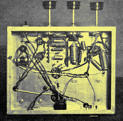
The underside of the amplifier
Construction of the amplifier should present no problems, since normal practice is followed. Heater wiring should be run in twisted pair dressed close to the chassis, and kept clear of grid circuit wiring. Short earth leads taken to common points for each stage were found sufficient to ensure satisfactory hum-free operation. Use is made of tag strips to mount or anchor small components conveniently. After the heater feeds, HT wiring and mains transformer wiring has been completed, the components for the tone control network should be wired, for they are then more accessible.
When switching on the amplifier for the first time it is necessary to ensure that the negative feedback connections on the secondary of the output transformer are correct. If a loud howl begins to develop as the amplifier warms up, it should be switched off immediately. Reversing the secondary winding connections as given in the Appendix should ensure correct feedback. If there is residual hum present, earthing the chassis should effectively remove it, though normally the amplifier can be run without an earth. Finally, never use the amplifier without a speaker connected, otherwise damage may be caused to the output valves.
Acknowledgements
The author Wishes to thank Mr Manners of the Valve Application Department, Standard Telephones & Cables Ltd. (Brimar Valve Division), and Mr Barnes of the Radio Division, The Telegraph Condenser Co. Ltd. for their helpful advice and assistance. Thanks are also due to Mr J L Warne for the photographs illustrating this article.
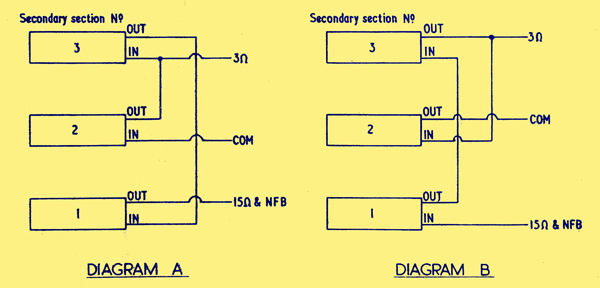
Appendix I
Output transformer secondary connections. If self-oscillation develops with the connections of diagram A they should be reversed to those shown in diagram B, and vice versa.
Appendix II - Winding details of the output transformer
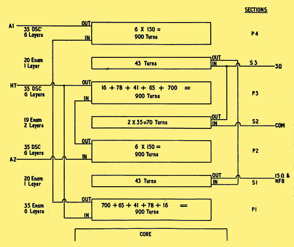
Disposition of Primary and Secondary sections
Core: 1 in stack of 1.25 in waste-free type stampings.
Tappings: At 15%, 18%, 20% and 24% of primary impedance for output valve. screen grids.
A Total secondary winding for 15Ω speaker, with tapping for 3Ω speaker.
Brief specification: Primary wound in four sections interleaved with secondary sections. Layers separated with one turn 1-mil paper, sections separated with two turns 5-mil Empire cloth. Two turns 5-mil Empire cloth over completed winding to finish.
Primary leads and taps brought out on end of one coil-cheek, secondary leads brought out on opposite side of same cheek, i.e., not opposite ends of coil layers.
All windings in same direction.
Winding details: Primary, section No. 1. Total 900 turns 35 swg. DSC in 6 layers, 150 turns per layer. Taps brought out at (A1) 700th turn, (B1) 765th turn, (C1) 806th turn, (D1) 884th turn from commencement of the winding, leaving 16 turns to end of winding.
Secondary, section No. 1. Total 43 turns 20 swg. Enam in one layer.
Primary, section No. 2. Total 900 turns 35 swg. DSC in 6 layers, 150 turns per layer, no taps.
Secondary, section No. 2. Total 70 turns 19 swg. Enam in 2 layers, 35 turns per layer.
Primary, section No. 3. Total 900 turns 35 swg. DSC in 6 layers, 150 turns per layer. Taps brought out at (D3) 16th turn, (C3) 94th turn, (B3) 135th turn, and (A3) 200th turn from commencement of the winding, leaving 700 turns to end of winding.
Secondary, section No. 3. Total 43 turns 20 swg. Enam in one layer.
Primary, section No. 4. Total 900 turns 35 swg. DSC in 6 layers, 150 turns per layer, no taps.
Windings to be inter-connected as shown in diagram.
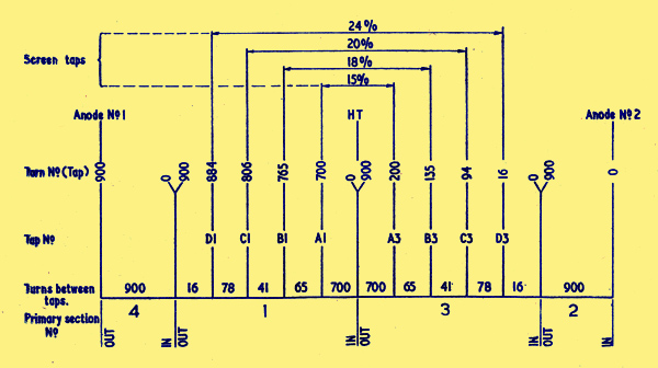
Details of Primary winding.
Addendum
Since this design was prepared some manufacturers have produced transformers for use in ultra-linear output stages. From data kindly supplied by Messrs. R F Gilson concerning their range of output transformers, some types are seen to be suitable for the Virtuoso, and could be used by those who do not wish to make their own transformer. No opportunity has arisen to test these transformers under working conditions, but a study of the published data reveals no reason why they should be other than entirely satisfactory.
Type WO.7l0/8K is rated for 8,000Ω primary load, with screen taps at 43%, of the turns ratio. Secondaries are rated for 2 x 3.7Ω and 15Ω. Primary inductance is of the order of 140H. This transformer is primarily for use with EL84 valves, which suggests a power handling capacity of some 15W. The price is #2 12s. 6d.
Type WO.710 is rated for 7,000Ω primary load, with screen taps at 20% of the turns ratio. In other respects it is similar to the WO.7l0/8K and is primarily for use with the Osram 912 amplifier. Its use with the Virtuoso may result in slight distortion due to the mismatch of primary load and the lower value of screen drive. The price is the same.
Type WO.892 is similar to the WO.710/8K. but with a slightly higher primary inductance of 180H. The power handling capacity is not stated, but it would not be likely to be lower than 15W. The price is #3 2s. 6d.
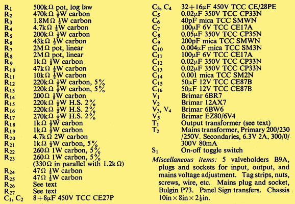
Components list
|